A mechanical lever frame inside the signal box at Knockcroghery in IrelandWaterloo station A signalbox, LSWR (Howden, Boys' Book of Locomotives, 1907)
Mechanical railway signalling installations rely on lever frames for their operation to interlock the signals, track locks[1] and points to allow the safe operation of trains in the area the signals control. Usually located in the signal box, the levers are operated either by the signalman or the pointsman.[citation needed]
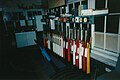
Lever frame of the signal box Hausen im Tal, Germany: the signals are operated by the red levers, black levers with Arabic numerals are for points and blue levers with Roman numerals are for track locks. The box on the right of the lever frame is used for manual block signalling; the smaller green levers are used for operating the route locks. The interlocking apparatus is in the box behind the levers.A three-lever ground frame at Kyle of Lochalsh, released by Annett's key
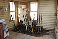
The lever frame is located in the signal box, which can be a building at ground level or a tower, separated from or connected to an existing station building. Early lever frames were also built as ground frames next to the track, without any form of shelter and were usually operated by traincrew and not permanently staffed. Especially in England, lever frames with the pivot underneath the floor of the signal box were common.[3]:122 This design's relatively short lever angle is a major disadvantage, as it requires more force to move the lever. Therefore, later, especially in Germany, lever frames with pivots inside the signaller's room were used, that allow for a lever angle of approximately 180°.[3]:123
By the movement of individual levers (or sometimes cranks),[3]:123 signals, points, track locks, level crossing gates or barriers and sometimes navigable movable bridges over waterways are operated via wires and rods. The signaller chooses the correct combination of points, facing point locks and signals to operate, which will control the movement of each train through their area of control. The lever frame contains interlocking designed to ensure that the levers cannot be operated to create a conflicting train movement. Each interlocking installation is individual and unique to the location controlled. The interlocking may be achieved mechanically or by electric lever locks, or (more usually) a combination of both.[citation needed]
Variants
Mechanical lever frames
Truro Signal Box lever frame
A mechanical lever frame is designed to harness mechanical advantage to operate switch points, signals or both under the protection of the interlocking logic. The levers are connected to field appliances via solid pipes or taut wires such that the full travel of the lever will reliably cause full travel in the appliance. Each lever is engaged with the interlocking logic such that movement of the lever is only possible when all necessary conditions are met. The interlocking may be mechanical, electric (via solenoids) or both with the apparatus being mounted horizontally behind the lever frame[3]:125 or vertically below it.
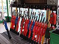
To assist the operator in determining their functions, each lever in a frame will generally be uniquely labelled, one common method being to number the levers in order from left to right. A lever's identification may be painted on its side or engraved on a badge or plate fitted either to the lever or behind it. This may be accompanied by a description of the lever's function. Usually, a large track diagram is positioned within easy view of the operator, which clearly shows each lever number adjacent to symbols representing the items of equipment that they operate. Levers are commonly coloured according to the type of equipment they control, the code of colours varying between different railway administrations. For example, in British practice, the following code generally applies: a red lever controls a stop signal or shunt signal, a yellow lever controls a distant signal, a black lever controls a set of points, a blue lever controls a facing point lock, and a white lever is spare. Brown levers are used to lock level crossing gates. Lever handles are usually of polished, unpainted steel, and signalmen operate them with a cloth to prevent rusting from the sweat on their hands.[4] In Germany, signal levers are red, whilst levers for points and track locks are usually blue, and route lock levers are green. Also, individual numbers and letters are used to indicate each individual item a lever operates in Germany as well.[3]:126
Some mechanical frames were combined with a set of electric levers or switches to more efficiently work electrically powered signals or other non-mechanically operated devices.[citation needed] Typically the switch points would be left under mechanical operation as the other devices used comparatively little electrical power and could be run off of batteries or a low capacity railroad-operated power system.[citation needed]
Power frames
Everglades Junction signal box with its Westinghouse Brake & Signal Co. Ltd. Style 'L' Power Lever Frame
A power operated interlocking frame uses some form of power assist to operate switches, signals and other interlocking appliances in the field. The power can come from hydraulic, pneumatic or electric sources with direct acting or low voltage electric control.[3]:250
In hydraulic lever frames, moving the lever operates a hydraulic valve rather than wires and rods. To prevent accidents, operating a set of points requires pulling the actual lever for the points and a secondary check lever. The points are then moved by a hydraulic motor. This type of power frame has the disadvantage of a relatively low distance between points and signal box (approximately 200–250m) and a slow operating speed. It was common in Italy and France only.[3]:250 Pneumatic lever frames have an operating principle that is related to that of hydraulic lever frames, however, instead of a hydraulic liquid, compressed air is used. The two types also share the same disadvantages such as pressurized tubing having to run directly between the field appliance and the lever frame. Electric control of a hydraulic or pneumatic actuator in the field was far simpler and more reliable, allowing for a greater distance between signal box and points. Whilst first being common in the United States due to work by the Union Switch & Signal corporation (a division of Westinghouse Air Brake Company), this system was later used in the United Kingdom and other Commonwealth nations where the Westinghouse Air Brake Company had a presence.[3]:251
In Austria, Siemens & Halske built a fully electric power frame in 1894, which does not rely on compressed air. Instead, electric motors move the points. Later, this system was also used in Germany.[3]:252 In the United States the Taylor Signal Corporation, later merged into General Railway Signal developed an electrically powered interlocking system that made use of mechanical slides to engage traditional mechanical locking. Union Switch and Signal later modified their electro-pneumatic system to all-electric as early as 1896.[citation needed]
A major issue with power frames was ensuring that the position of the levers on the frame correctly represented the position of the switch or other appliance in the field. Unlike a mechanical linkage, pneumatic or hydraulic lines could leak and cause points to drift out of correspondence with disastrous consequences. The Taylor/GRS electric power frame system used a feature called "dynamic indication" where the counter-electromotive force generated when the electric motor reached the limit of travel would signal the interlocking logic that the points had finished moving, but not the position of the points on an ongoing basis.[5] This and other open loop systems designed in the 19th and early 20th centuries to save on costly relays, were replaced by closed loop systems after a number of accidents. In North America this is known as "Switch-Signal" protection and any change in the position of a field appliance will immediately set the electric signals controlled by a power frame to danger.[6]
Railway Signal Company lever frame at Cromer Beach signal box, Cromer, UK
View of the frame in the locking room showing how it is installed within the signal box. Oulton Broad Swing Bridge signal box, Lowestoft, UK
Another view in the locking room at Oulton Broad Swing Bridge, Lowestoft, UK
Signal box interior, Truro, UK
Derby Road Signal box, Ipswich, UK, showing the McKenzie & Holland frame, taken in 1997. Opened in 1891 by the Great Eastern Railway. Abolished and demolished in 1999
↑ Fenner, Wolfgang; Naumann, Peter; Trinckauf, Jochen (2011). Bahnsicherungstechnik: Steuern, Sichern und Überwachen von Fahrwegen und Fahrgeschwindigkeiten im Schienenverkehr (in German). John Wiley & Sons. p.89. ISBN9783895786839.
↑ Stephen, Paul (July 2018). "From the Files: Shrewsbury's Record-Breakers". RailMagazine.com. Retrieved 20 September 2018. This place is fairly unique these days in being double-manned, but with 92 levers to operate it keeps us fairly busy and you soon work through the shoe leather.
1 2 3 4 5 6 7 8 9 Cauer, Wilhelm Adolf Eduard (1922). Otzen, Robert (ed.). "Sicherungsanlagen im Eisenbahnbetriebe". Handbibliothek für Bauingenieure. Berlin/Heidelberg: Springer. ISBN9783662344903.{{cite journal}}: ISBN / Date incompatibility (help)
This page is based on this Wikipedia article Text is available under the CC BY-SA 4.0 license; additional terms may apply. Images, videos and audio are available under their respective licenses.