The basic principle behind the track circuit lies in the connection of the two rails by the wheels and axle of locomotives and rolling stock to short an electrical circuit. This circuit is monitored by electrical equipment to detect the absence of the trains. Since this is a safety appliance, fail-safe operation is crucial. Hence the circuit is designed to indicate the presence of a train when failures occur. On the other hand, false occupancy readings are disruptive to railway operations and must be minimized.
Track circuits allow railway signalling systems to operate semi-automatically, by displaying signals for trains to slow or stop in the presence of occupied track ahead of them. They help prevent dispatchers and operators from causing accidents, both by informing them of track occupancy and by preventing signals from displaying unsafe indications.
Basic circuit
Schematic drawing of track circuit for unoccupied block (series resistor next to battery not shown)Schematic drawing of occupied track circuit (series resistor next to battery not shown)
A track circuit typically has power applied to each rail and a relay coil wired across them. When no train is present, the relay is energised by the current flowing from the power source through the rails. When a train is present, its axles short (shunt) the rails together. The current to the track relay coil drops, and it is de-energised. Circuits through the relay contacts therefore report whether or not the track is occupied.
Each circuit detects a defined section of track, such as a block. These sections are separated by insulated joints, usually in both rails. To prevent one circuit from falsely powering another in the event of insulation failure, the electrical polarity is usually reversed from one section to an adjacent section. Circuits are powered at low voltages (1.5 to 12V DC). The relays and the power supply are attached to opposite ends of the section to prevent broken rails from electrically isolating part of the track from the circuit. A series resistor limits the current when the track circuit is short-circuited.
Circuits under electrification
In some railway electrification schemes, one or both of the running rails are used to carry the return traction current. This precludes use of the basic DC track circuit because the substantial traction currents overwhelm the very small track circuit currents.
Where DC traction is used on the running line or on tracks in close proximity then DC track circuits cannot be used; similarly if 50Hz AC electrification is used then 50Hz AC track circuits cannot be used.
To accommodate this, AC track circuits use alternating current (AC) signals instead of direct current (DC) but typically, the AC frequency is in the range of audio frequencies, from 91Hz up to 10kHz. The relays are arranged to detect the selected frequency and to ignore DC and AC traction frequency signals. Again, fail-safe principles dictate that the relay interprets the presence of the signal as unoccupied track, whereas a lack of a signal indicates the presence of a train. The AC signal can be coded and locomotives equipped with inductive pickups to create a cab signalling system.
There are two common approaches to provide a continuous path for traction current that spans multiple track circuit blocks. The simplest method installs insulated track circuit joints on only one of the two rails with the second being a path for the return current and a ground for the track circuit rail. This has the disadvantage of only being able to detect breaks in one rail so the more popular two rail system uses impedance bonds to permit traction current to pass between isolated track circuit blocks while blocking current at track circuit frequencies.
AC circuits are sometimes used in areas where conditions introduce stray currents, which interfere with DC track circuits.
Jointless track circuits
Electric "joints" of jointless track circuits on Shanghai Metro. Left: Wee-Z Bond of a GRS audio frequency track circuit; Right: S-Bond of an Alstom Digicode track circuit
Modern track is often continuously welded, the joints being welded during installation. This offers many benefits, except to the signalling system, which no longer has natural breaks in the rail to form block sections. The only method to form discrete blocks in this scenario is to use different audio frequencies (AF) in each block section. To prevent the audio signal from one section passing into an adjacent section, pairs of tuned circuits are connected across the rails at the section boundary. The tuned circuit often incorporates the circuit to either apply the transmitted signal to the track or recover the received signal from the other end of the section.
Consider a railway with two block sections as in the diagram. Section 1 has frequency A injected at the left-hand end and received at the right-hand end. Section 2 continues from the right hand end of section 1 where frequency B is injected and then received at the right-hand end of section 2.
Track circuited railway with two block sections
There is often a gap between where frequency A is received and frequency B is injected. This is referred to as a 'tuned zone' and is a section of track where the amplitude of frequency A reduces in the direction of section 2 and the amplitude of frequency B reduces in the direction of section 1. The tuned zone can be of the order of 20m long.
Advantages of jointless track circuits:
Eliminates insulated block joints, a component liable to mechanical failure (both of insulation and by introducing stress to adjoining rails) and maintenance.
In electrified areas, jointless track circuits require fewer impedance bonds than any other double rail traction return track circuits.
Disadvantages of jointless track circuits:
Restrictions on placing impedance bonds, hence any connection for electrification purposes, in or near tuned zones as this may upset the filter properties of the tuned zone.
Electronic circuits are more vulnerable to lightning strikes.
CSEE UM71
Tuning unit of a ZPW-2000 (Chinese variant of UW71) track circuit and a sign indicating "do not stop at circuit boundary", where loss-of-shunt may occur.
CSEE (now Ansaldo STS) UM71 is another kind of jointless track circuit. It uses 1700Hz and 2300Hz on one track and 2000Hz and 2600Hz on the other.[1] To reduce the chance of stray currents causing a wrong side failure the modulation frequency is calculated by dividing the base frequency by 128. Different rates of modulation can be detected by equipment on the trains and used for automatic train control, so long as the transmitter end (Tx) is at the front of the train.
The EBItrack (formerly TI21) and Westinghouse FS2500 jointless track circuits are similar to the UM71.
Data pickup unit
Data pickup unit CSEE; end view
A jointless track circuit such as the CSEE can be divided with a data pickup unit (DPU), which is cheaper than splitting it into two track circuits. A DPU avoids the need to change the frequency of a whole series of track circuits in a cascade. The DPU consists of a tuned coil which detects the presence or absence of current in the adjacent rail and picks up or drops a relay accordingly. One use of DPUs is for timing circuits. Each track circuit frequency has its own DPU tuned to that frequency. DPUs can be located almost anywhere; they overcome the limitation that jointless tracks have a minimum length.
DC coded track circuits
In non-electrified areas, DC coded track circuits may be used. These modulate the current going from the powersource end to the relay end and control the signals and cab signals without the need for line wires. The modulated currents can be detected by equipment connected to the track to provide signaling and indication information to activate proper cab signalling if available. [2] They can be overlain by predictor systems to operate level crossings.[3]
Where the length of a section exceeds the practical length of a track circuit, cut tracks can be provided. With a cut track, the relay of the last track cuts the powersource feed of the second last track circuit, and so on. Cut tracks are only suitable for unidirectional tracks.
Track circuits with ballast contamination will be shorter than those with good ballast, thus needing more cut tracks.
High-voltage tracks
One common brand of high-voltage impulse track (HVIT) circuit is made by Jeumont-Schneider. The high voltage penetrates rust and other problems.
The HVIT transmits two pulses alternately, a narrow positive one at about 100V DC and a negative broader one at about 30V DC. The energy of the two pulses is the same. At the receiver end an R-C circuit integrates the two pulses, which must be of the correct proportions for the relay to pick up. The R-C circuits check that the positive and negative pulses are in correct phase. The two pulses operate at about 1Hz.
The circuit operates on AC and DC electrified lines, with additional equipment.
Single rail and double rail
In non-electrified areas, insulated blockjoints come in pairs, one on each rail.
In electrified areas, a workaround is needed to allow the traction current, of the order of thousands of amperes, to return to the substation. This may be achieved by having no insulated block joints in one of the rails, called the return rail.
If both rails are needed to carry the heavy traction return current, then insulated blockjoints are provided in both rails, and impedance bonds are provided to carry the traction current around the insulated joints. Impedance bonds are essentially centre-tapped coils, which offer low impedance to traction current at say 50Hz, while offering high impedance to signalling current at say 1.7kHz.
Failure modes and prevention
Wheels and brakes
Railway wheels are made from steel and provide a good short circuit from rail to rail (shunt resistance).
Longer trains with more wheels have better conductivity. Short trains, light railmotors or single engines can be a problem. In New Zealand there were problems with light Rm class railmotors not always being detected; see Railway signalling in New Zealand. Trains with a single Budd railmotor, which are also lightweight, and with discbrakes, had some problems when they stopped, and had to make a double stop to ensure good contact with the rails.[citation needed]
Cast iron brake shoes tend to clean the wheels of non-conductive debris (such as leaves and sand-based traction compounds), while disc brakes do not. As a result, some disc-braked vehicles have "scrubber pads" cleaning the wheels to aid in proper track circuit operation.[citation needed]
Relays
Track circuit relays, referred to by signal maintainers as "vital relays," are specially designed to reduce the chance of wrong-side failures. They may, for example, have carbon-silver contacts to reduce the likelihood of the wrong contacts welding shut after power surges and lightning strikes.
Circuit failures
The circuit is designed so the vast majority of failures will cause a "track occupied" indication (known as a right-side failure). For example:
A broken rail or wire will break the circuit between the power supply and the relay, de-energizing the relay. See exception below.
A failure in the power supply will de-energize the relay.
A short across the rails or between adjacent track sections will de-energize the relay.
On the other hand, failure modes which prevent the circuit from detecting trains (known as a wrong-side failure) are possible. Examples include:
Mechanical failure of the relay, causing the relay to be stuck in the "track clear" position even when the track is occupied.
One perspex case warped in the heat, and touched the relay contacts, holding them up.
Another Q-series "miniature" relay saw a metal washer slip off and jam the relay contacts up; the half-washers had to be replaced by full-circle washers.
Conditions which partially or completely insulate the wheels from the rail, such as rust, sand, or dry leaves on the rails. This is also known as "poor shunting" ("failure to shunt" in North America and Australia). Sanding gear which operates on all wheels of an engine traveling light can temporarily insulate it from the rails until the sanding ceases and the locomotive has moved further down the track.
Where multiple parallel paths exist for traction return purposes broken rail detection will be lost for the rail that is used for the traction return. If more than one break occurs in that rail a false clear can occur when the train is between the breaks.
Conditions in the trackbed (roadbed) which create stray electrical signals, such as muddy ballast (which can generate a "battery effect") or parasitic electrical currents from nearby power transmission lines.
Equipment which is not heavy enough to make good electrical contact (shunt failure) or whose wheels must be electrically insulated.
A rail break between the insulated rail joint and the track circuit feed wiring would not be detected.
Failure modes that result in an incorrect "track clear" signal (known usually in North America as a "false clear") may allow a train to enter an occupied block, creating the risk of a collision. Wheel scale and short trains may also be a problem. They may also cause the warning systems at a grade crossing to fail to activate. This is why in UK practice, a treadle is also used in crossing circuitry.
Different means are used to respond to these types of failures. For example, the relays are designed to a very high level of reliability. In areas with electrical problems, different types of track circuits may be used which are less susceptible to interference. Speeds may be restricted when and where fallen leaves are an issue. Traffic may be embargoed to let equipment pass which does not reliably shunt the rails.
Sabotage is possible. In the 1995 Palo Verde derailment, saboteurs electrically connected sections of rail which they had displaced to conceal the breaks in the track they had made. The track circuit therefore did not detect the breaks, and the engine driver was not given a "Stop" indication. Another form of sabotage, not intended to cause a train crash but merely to make trains stop and slow down unnecessarily in an effort to sabotage an economy or potential injuries, is to tie a wire between the 2 rails, causing a false obstruction signal.[5][6]
Railhead contamination and rust
The track circuit relies upon an adequate electrical contact between the rail and the wheel; contamination can insulate the one from the other. A common problem is fallen leaves, though there have been cases where crushed insects have also caused detection failures.[7]
A more persistent problem is rust. Usually the railhead is kept clean of rust by the regular passage of trains' wheels. Lines which are not used regularly can become so rusty as to prevent vehicles being detected. Seldom-used points and crossovers and the extremities of terminal platform lines are also prone to rusting. Measures to overcome this include:
Depression bars or treadles to detect vehicles; these are mechanical;
Stainless steel strips (often zig zag in shape) welded on the railheads; stainless steel does not rust;
High-voltage impulse track circuits;
Track circuit assistor (TCA) - a train-mounted system that breaks down the resistance of the rust layer;
Tunnel sticks whereby a track circuit cannot pick up unless a train is detected in the next track circuit.
Scale
Insulated blockjoints can be bridged by wheel scale in some circumstances causing one or two track circuits to fail. This problem may be reduced by having a pair of blockjoints in series about 4m apart. The short 4m section would not itself be track circuited.[8]
Immunization
Electric locomotives must avoid generating noise in the frequencies that track circuits use. The SNCB Class 13 had such problems.
Transitory problems
A short, lightweight and fast train passing over an insulated blockjoint may disappear from the departing track circuit before it appears in the arriving track circuit, allowing false clear signals to be given. This problem can be overcome by introducing a time delay of say 1–2 seconds into the departing track circuit. Electronic track circuits such as the CSEE can easily incorporate such a time delay.
Siding turnout
It is sometimes convenient to wire the detectors of a set of points through the track circuit over those points. This can be done in one of two ways:
A contact of the points detector can shunt the track circuit when the points are reverse, putting the signals to red, however this is not failsafe.
The track circuit can be split with extra blockjoints and the detectors in the points complete the track circuit when the points are normal and the signal is entitled to receive a green light. This is partially fail-safe.
A second relay can be installed on the turnout, with its contacts wired in series with the main relay. This is fail-safe but expensive.[dubious–discuss]
Track-circuit operating clips
A simple piece of safety equipment which is carried by all heavy rail trains in Britain is a track-circuit operating clip (TCOC).[9] This is a length of wire connecting two metal spring clips that clip onto a rail. In the event of accident or obstruction a clip applied to both rails will indicate that that line is occupied, putting the signal for that section to danger.
Emergency protection procedure[9] in the UK requires TCOCs to be placed on all affected running lines if contact cannot be made immediately with the signaller following an accident where adjacent lines are blocked.
TCOCs are ineffective where train detection is not by means of track circuits, such as axle counters or treadles.
History
The first use of track circuiting was by William Robert Sykes on a short stretch of track of the London Chatham and Dover Railway at Brixton in 1864.[10] The failsafe track circuit was invented in 1872 by William Robinson, an American electrical and mechanical engineer. His introduction of a trustworthy method of block occupancy detection was key to the development of the automatic signalling systems now in nearly universal use.[11]:3ff
The first railway signals were manually operated by signal tenders or station agents. When to change the signal aspect was often left to the judgement of the operator. Human error or inattentiveness occasionally resulted in improper signalling and train collisions.
The introduction of the telegraph during the mid-nineteenth century showed that information could be electrically conveyed over considerable distance, spurring the investigation into methods of electrically controlling railway signals. Although several systems were developed prior to Robinson's, none could automatically respond to train movements.
Robinson first demonstrated a fully automatic railway signalling system in model form in 1870. A full-sized version was subsequently installed on the Philadelphia and Erie Railroad at Ludlow, Pennsylvania (aka Kinzua, PA), where it proved to be practical. His design consisted of electrically operated discs located atop small trackside signal huts, and was based on an open track circuit. When no train was within the block no power was applied to the signal, indicating a clear track.[11]:4
An inherent weakness of this arrangement was that it could fail in an unsafe state. For example, a broken wire in the track circuit would falsely indicate that no train was in the block, even if one was. Recognizing this, Robinson devised the closed loop track circuit described above, and in 1872, installed it in place of the previous circuit. The result was a fully automatic, failsafe signalling system that was the prototype for subsequent development.[11]:6–9
Although a pioneer in the use of signals controlling trains, the UK was slow to adopt Robinson's design. At the time, many carriages on UK railways had wooden axles and/or wheels with wooden hubs, making them incompatible with track circuits.
Accidents
Caused by lack of track circuits
Numerous accidents would have been prevented by the provision of track circuits, including:
Much rarer are accidents caused when the track circuits themselves fail. For example:
Cowan rail disaster, which occurred when sand on the rails insulated the wheels from the rails, causing a failure to shunt that allowed a trailing block signal to improperly display a clear aspect, resulting in a rear-end collision.
Moravany railway crash, occurred in Moravany railway station. Broken sand dispenser caused a layer of sand being created on the rail, making it lose the shunt. The station equipment interpreted this as the track is free and allowed another train in to proceed into the station, which then crashed into the previous train from behind.[12]
Because Track circuits operate by passing a current through one or both of the tracks, they can sometimes detect if a rail has broken completely. However, if the break is only partial or is at a turnout (set of points) detection may not be possible.
Big Bayou Canot rail accident (1993) - undetected unbroken but badly twisted continuous welded rail on a bridge that still indicated a clear condition to the signal.
In electrical engineering, a transformer is a passive component that transfers electrical energy from one electrical circuit to another circuit, or multiple circuits. A varying current in any coil of the transformer produces a varying magnetic flux in the transformer's core, which induces a varying electromotive force (EMF) across any other coils wound around the same core. Electrical energy can be transferred between separate coils without a metallic (conductive) connection between the two circuits. Faraday's law of induction, discovered in 1831, describes the induced voltage effect in any coil due to a changing magnetic flux encircled by the coil.
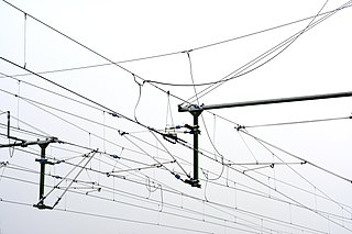
An overhead line or overhead wire is an electrical cable that is used to transmit electrical energy to electric locomotives, electric multiple units, trolleybuses or trams. The generic term used by the International Union of Railways for the technology is overhead line. It is known variously as overhead catenary, overhead contact line (OCL), overhead contact system (OCS), overhead equipment (OHE), overhead line equipment, overhead lines (OHL), overhead wiring (OHW), traction wire, and trolley wire.
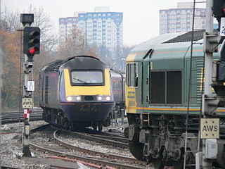
Railway signalling (BE), or railroad signaling (AE), is a system used to control the movement of railway traffic. Trains move on fixed rails, making them uniquely susceptible to collision. This susceptibility is exacerbated by the enormous weight and inertia of a train, which makes it difficult to quickly stop when encountering an obstacle. In the UK, the Regulation of Railways Act 1889 introduced a series of requirements on matters such as the implementation of interlocked block signalling and other safety measures as a direct result of the Armagh rail disaster in that year.
A third rail, also known as a live rail, electric rail or conductor rail, is a method of providing electric power to a railway locomotive or train, through a semi-continuous rigid conductor placed alongside or between the rails of a railway track. It is used typically in a mass transit or rapid transit system, which has alignments in its own corridors, fully or almost fully segregated from the outside environment. Third-rail systems are usually supplied from direct current electricity.
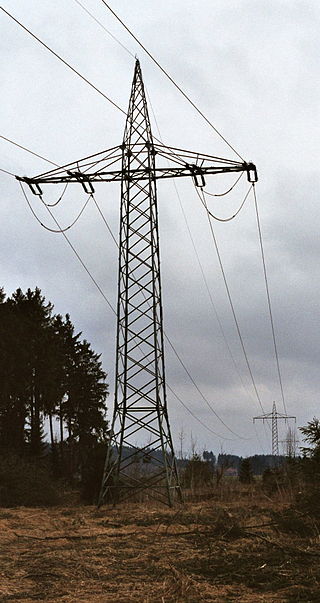
Railway electrification is the use of electric power for the propulsion of rail transport. Electric railways use either electric locomotives, electric multiple units or both. Electricity is typically generated in large and relatively efficient generating stations, transmitted to the railway network and distributed to the trains. Some electric railways have their own dedicated generating stations and transmission lines, but most purchase power from an electric utility. The railway usually provides its own distribution lines, switches, and transformers.
The use of a third rail in rail transport modelling is a technique that was once applied, in order to facilitate easier wiring.
A traction motor is an electric motor used for propulsion of a vehicle, such as locomotives, electric or hydrogen vehicles, or electric multiple unit trains.
The Cowan rail accident occurred at 7:20pm on 6 May 1990 when the 3801 Limited special steam passenger train returning from the Morpeth Jazz Festival was struck in the rear by the following CityRail inter-urban passenger service. The steam train had stalled while attempting to climb the steep gradient from the Hawkesbury River to Cowan, New South Wales, and it was found that sand applied to the rails to regain traction had interfered with the signals and given the following train a false clear indication.
A wrong-side failure describes a failure condition in a piece of railway signalling equipment that results in an unsafe state. A typical example would be a signal showing a 'proceed' aspect when it should be showing a 'stop' or 'danger' aspect, resulting in a "false clear".
An induction or inductive loop is an electromagnetic communication or detection system which uses a moving magnet or an alternating current to induce an electric current in a nearby wire. Induction loops are used for transmission and reception of communication signals, or for detection of metal objects in metal detectors or vehicle presence indicators. A common modern use for induction loops is to provide hearing assistance to hearing-aid users.
A traction network or traction power network is an electricity grid for the supply of electrified rail networks. The installation of a separate traction network generally is done only if the railway in question uses alternating current (AC) with a frequency lower than that of the national grid, such as in Germany, Austria and Switzerland.
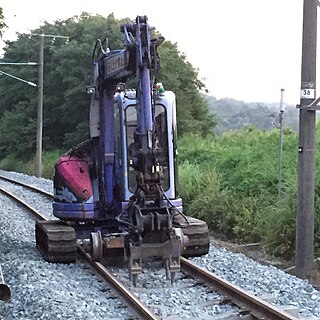
A road–rail vehicle or a rail–road vehicle is a dual-mode vehicle which can operate both on rail tracks and roads. They are also known as two-way vehicles, hi-rail, and rail and road vehicles.
Transmission Voie-Machine (TVM)('Track-to-train transmission') is a form of in-cab signalling originally deployed in France and is mainly used on high-speed railway lines. TVM-300 was the first version, followed by TVM-430.
An axle counter is a system used in railway signalling to detect the clear or occupied status of a section of track between two points. The system generally consists of a wheel sensor and an evaluation unit for counting the axles of the train both into and out of the section. They are often used to replace a track circuit.
Railway electric traction describes the various types of locomotive and multiple units that are used on electrification systems around the world.
Digital model railway control systems are an alternative to control a layout and simplify the wiring and add more flexibility in operations. A number of control systems are available to operate locomotives on model railways. Analog systems where the speed and the direction of a train is controlled by adjusting the voltage on the track are still popular while they have recently given way to control systems based on computer technology.
Pulse code cab signaling is a form of cab signaling technology developed in the United States by the Union Switch and Signal corporation for the Pennsylvania Railroad in the 1920s. The 4-aspect system widely adopted by the PRR and its successor railroads has become the dominant railroad cab signaling system in North America with versions of the technology also being adopted in Europe and rapid transit systems. In its home territory on former PRR successor Conrail owned lines and on railroads operating under the NORAC Rulebook it is known simply as Cab Signaling System or CSS.
Level crossing signals are electronic warning devices for road vehicles at railroad level crossings.
ALSN is a train control system used widely on the main lines of the ex-Soviet states. It uses modulated pulses inducted into rails similar to the Italian RS4 Codici and American Pulse Code Cab Signaling. On high-speed lines the variant ALS-EN (АЛС-ЕН) is used which takes advantage of a double phase difference modulation of the carrier wave.
Amtrak’s 60 Hz traction power system operates along the Northeast Corridor between New Haven, Connecticut, and Boston, Massachusetts. This system was built by Amtrak in the late 1990s and supplies locomotives with power from an overhead catenary system at 25 kV alternating current with at 60 Hz, the standard frequency in North America. The system is also known as the Northend Electrification, in contrast to Amtrak's 25 Hz traction power system that runs between New York City and Washington, D.C., which is known as the Southend Electrification system.
1 2 National Transportation Safety Board (NTSB), Washington, D.C. (2009-09-22). "Safety Recommendations R-09-15 and R-09-16." Letter from Deborah A.P. Hersman, Chairman, NTSB, to John B. Catoe, Jr., General Manager, Washington Metropolitan Area Transit Authority.
This page is based on this Wikipedia article Text is available under the CC BY-SA 4.0 license; additional terms may apply. Images, videos and audio are available under their respective licenses.