Axle counter

Last updated
An axle counter detection point in the UK AxleCounter.jpg
An axle counter detection point in the UK
Axle counter for automatic railway crossing (Slovenia) Stevec osi.jpg
Axle counter for automatic railway crossing (Slovenia)

An axle counter is a system used in railway signalling to detect the clear or occupied status of a section of track between two points. The system generally consists of a wheel sensor (one for each end of the section) and an evaluation unit for counting the axles of the train both into and out of the section. They are often used to replace a track circuit.

Contents

Principles and operation

An axle counter consists of a sensor, which detects the individual axles of a train by mechanical, electrical or even fibre optic method, and an evaluator which counts the axles passing into and out of a rail section. The evaluator may also convert the analogue signal of the axle sensor into a digital signal. However, in some cases there is a separate unit which performs this task.

The system is set up by having an axle counter sensor installed at each end of a section. As each train axle passes the axle counter sensor at the start of the section, a counter increments. An axle counter sensor comprises two independent sensors (so the device can detect the direction and speed of a train by the order and time in which the sensors are passed). As the train passes a similar axle counter sensor at the end of the section, the system compares count at the end of the section with that recorded at the beginning. If the two counts are the same, the section is presumed to be clear.

This process is carried out by safety-critical centrally located computers, called "evaluators", with the axle counter sensors located at the required sites in the field. The axle counter sensors are either connected to the evaluator via dedicated copper cable or via a telecommunications transmission system. That allows the axle counter sensors to be located a significant distance from the evaluator, and is useful when using centralised interlocking equipment, but less so when signalling equipment is situated beside the line in equipment cabinets.

Applications

Track vacancy detection

Railway signalling

The most common use for axle counters is in railway signalling for track vacancy detection. It is a form of block signalling, which does not permit two trains to be within the same section of track (block) at the same time. Block signalling decreases the chance of collision, because dividing the track into blocks ensures there is always enough space between trains to allow one to stop before it hits one in front. [1]

Railway crossings

Axle counters are also used to switch on and switch off warning equipment at level crossings, closing the crossing to pedestrian and motor vehicles when the presence of a train is detected, and allowing them to open when the train has passed over the crossing. [2]

Switch protection in rail yards

Axle counters are used in rail yards to detect train cars as they are sorted. Axle counters are placed on the track before each switch and on each track that exits the switch. Rail yard management software uses occupancy data from the axle counters to lock switches and prevent cars from being routed to tracks that are occupied by other cars.

Advantages

Unlike traditional track circuits, axle counters do not require insulated rail joints to be installed. This avoids breaking the continuity of long sections of welded rail to allow insulated joints to be inserted.

Electrified Railways

Axle counters are particularly useful on electrified railways as they eliminate the need for traction bonding and impedance bonds. Axle counters require no bonding and less cabling in comparison to track circuits, and are therefore generally less expensive to install and maintain.

Insulated Rail Joints

Axle counters eliminate most railjoints (IRJ) which are a weak point on the track.

Railhead Contamination

Axle counters do not suffer problems with railhead contamination due to rust, grease or compacted leaf residue. Sometimes a train puts down anti-slip sand to aid deceleration while braking, but the sand contaminates the rail and the track circuit stops working. Axle counters are immune to those problems because they do not rely on the contact of wheel with the rail head to provide an electrical circuit.

Better Performance in Wet Conditions

Axle counters are used in wet tunnels (such as the Severn Tunnel), where ordinary track circuits are unreliable. Axle counters are also useful on steel structures (such as the Forth Bridge), which may prevent the normal operation of track circuits if insulating the rails from the structure proves impracticable. Axle counters are also useful on long sections where the need for several intermediate track circuits may be saved. An axle counter can go up to around 10,000 metres (33,000 ft) from the evaluation unit when connected directly. However, with the addition of an Ethernet network, the distance is limited by the transmission system.

Disadvantages

For various reasons, such as a power failure, axle counters may 'forget' how many axles are in a section. A manual override is therefore necessary to reset the system. This manual override introduces the human element which may be unreliable. An accident which occurred in the Severn Tunnel is thought to have been due to the improper restoration of an axle counter. That was not proven during the subsequent inquiry, however. In older installations, the evaluators may use 8-bit logic, causing numeric overflow when a train with 256 or more axles passes the axle counter. As a result, that train would not be detected. That imposes a length limit of 255 axles on each train. [3] More modern systems are not restricted by train wheel numbers.

Turnouts

Where there are interlocked turnouts, an axle counter unit needs to be provided for each leg of that turnout. On lines with non-interlocked/hand-operated switches, detection of the switch points would have to be monitored separately, whereas on track-circuited lines misaligned points can be set to automatically break the track circuit.

Broken rails

A track circuit system does facilitate the detection of many, but not all, kinds of broken rails, though only to a limited extent in AC traction areas, and not in the common rail in DC traction areas. By contrast, axle counters cannot detect broken rails at all. Ordinary track circuits do have a blind spot of about a metre in length from the wiring connections to the insulated rail joint (IRJ).

Siding and shunting movements

Axle counters have problems maintaining correct counts when train wheels stop directly on the counter mechanism. That is known as 'wheel rock', and can prove problematic at stations or other areas where cars are shunted, joined and divided. Also, where main lines have switches to siding, spur or loop tracks, extra counters will need to be deployed to detect trains entering or exiting the line, whereas the same infrastructure using track circuits needs no special attention.

In Auckland, New Zealand, axle counters have been used on all lines where track circuits are required, except for special places where Hi Rail maintenance vehicles either on or off track. All road crossing tracks at public level crossings are deemed to be Hi Rail access points and a short single rail DC track circuit is used. There are also several single rail DC track circuits at places not at level crossings where Hi Rail vehicles can access the track.

Electromagnetic brakes

Magnetic brakes are used on high speed \ higher speed trains with a maximum speed greater than 160 kilometres per hour (100 mph). These are physically large pieces of metal mounted on the bogie of the vehicle, only a few centimetres above the track. They can sometimes be mistakenly detected by axle counters as another axle. This can happen at only one end a track block, because of magnetic field curvature, defects of track geometry,or other issues, leading the signalling system to become confused, and also requiring reset of the detection memory. Modern axle counters are 'eddy current' brake-proof and the magnetic effect of the braking system as described above is overcome, with count information remaining stable even when a vehicle fitted with magnetic brakes is braking whilst traversing the detection point.

Installation

One method of mounting an axle counter sensor is to drill through the rail, however this is often seen as time-consuming, as well as having the disadvantage of weakening the structure of the rail. However. it does eliminate the need for levelling, which can help reduce maintenance costs. [4]

Another installation method is to mount the Axle Counter Sensor onto a mount which clamps to both sides of the rail from underneath. That is quicker and easier to mount in the right conditions, but can mean more frequent checks to ensure correct positioning is maintained. [5]

Reset and restoration

There are four methods of securing the reset and restoration of axle counters into service:

Most countries use a variation of the above four methods, sometimes with varying amounts of automation or human input.

History

Axle counting initially started with treadle-like mechanisms. They consisted of a mechanical contact device mounted on the inside of the foot of rail; the wheel flange running over the device actuated a lever. However, they were susceptible to errors and were replaced in Europe at the end of the 19th century by hydraulic rail contacts. [7]

Hydraulic rail contacts were actuated by the deflection of the rail caused by axle load running over the tracks. The first cylinders were filled with mercury; later, hydraulic oil was used. They were then replaced by pneumatically operated switching elements. [7]

In pneumatic axle counting systems, pistons were actuated by specific loads and speeds. They proved limited in application, and therefore from the 1950s onwards were replaced by magnetic contacts. [7] Up to that point, track circuits always had a big edge when it came to reliability.

Magnetic contacts were the first contactless switching devices. They were known as "axle counting magnets". The iron wheel flanges triggered an actuation by interrupting a magnetic field. The first US patent for an axle counter, filed on 3 June 1960 by Ernst Hofstetter and Kurt Haas, [8] was for a device of this type. During this time, inductive methods were also being produced based on transformers. During the 1970s, developments in the electronics field as well as the introduction of integrated circuits allowed the design of the axle counters currently used. [7]

See also

Related Research Articles

<span class="mw-page-title-main">Anti-lock braking system</span> Safety anti-skid braking system used on aerospace and land vehicles

An anti-lock braking system (ABS) is a safety anti-skid braking system used on aircraft and on land vehicles, such as cars, motorcycles, trucks, and buses. ABS operates by preventing the wheels from locking up during braking, thereby maintaining tractive contact with the road surface and allowing the driver to maintain more control over the vehicle.

<span class="mw-page-title-main">Railroad switch</span> Mechanism to transfer trains from one track to another

A railroad switch (AE), turnout, or [set of] points (CE) is a mechanical installation enabling railway trains to be guided from one track to another, such as at a railway junction or where a spur or siding branches off.

<span class="mw-page-title-main">Tachometer</span> Instrument measuring the rotation speed of a shaft or disk

A tachometer is an instrument measuring the rotation speed of a shaft or disk, as in a motor or other machine. The device usually displays the revolutions per minute (RPM) on a calibrated analogue dial, but digital displays are increasingly common.

<span class="mw-page-title-main">Hall effect sensor</span> Devices that measure magnetic field strength using the Hall effect

A Hall effect sensor is any sensor incorporating one or more Hall elements, each which produce a voltage proportional to one axial component of the magnetic field vector B using the Hall effect.

<span class="mw-page-title-main">Railway signalling</span> The principle of signals used to control railway traffic

Railway signalling (BE), or railroad signaling (AE), is a system used to control the movement of railway traffic. Trains move on fixed rails, making them uniquely susceptible to collision. This susceptibility is exacerbated by the enormous weight and inertia of a train, which makes it difficult to quickly stop when encountering an obstacle. In the UK, the Regulation of Railways Act 1889 introduced a series of requirements on matters such as the implementation of interlocked block signalling and other safety measures as a direct result of the Armagh rail disaster in that year.

Rail transport terms are a form of technical terminology applied to railways. Although many terms are uniform across different nations and companies, they are by no means universal, with differences often originating from parallel development of rail transport systems in different parts of the world, and in the national origins of the engineers and managers who built the inaugural rail infrastructure. An example is the term railroad, used in North America, and railway, generally used in English-speaking countries outside North America and by the International Union of Railways. In English-speaking countries outside the United Kingdom, a mixture of US and UK terms may exist.

<span class="mw-page-title-main">Emergency brake (train)</span>

On trains, the expression emergency brake has several meanings:

<span class="mw-page-title-main">Automatic Warning System</span>

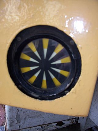
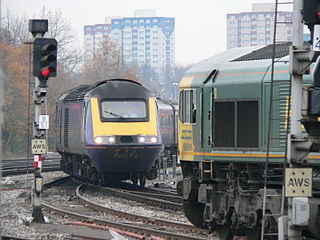
Automatic Warning System (AWS) is a railway safety system invented and predominantly used in the United Kingdom. It provides a train driver with an audible indication of whether the next signal they are approaching is clear or at caution. Depending on the upcoming signal state, the AWS will either produce a 'horn' sound, or a 'bell' sound. If the train driver fails to acknowledge a warning indication, an emergency brake application is initiated by the AWS. However if the driver correctly acknowledges the warning indication by pressing an acknowledgement button, then a visual 'sunflower' is displayed to the driver, as a reminder of the warning.

An induction or inductive loop is an electromagnetic communication or detection system which uses a moving magnet or an alternating current to induce an electric current in a nearby wire. Induction loops are used for transmission and reception of communication signals, or for detection of metal objects in metal detectors or vehicle presence indicators. A common modern use for induction loops is to provide hearing assistance to hearing-aid users.

<span class="mw-page-title-main">Track circuit</span> Electrical device used to detect the presence of trains on rail tracks

A track circuit is an electrical device used to prove the absence of a train on rail tracks to signallers and control relevant signals. An alternative to track circuits are axle counters.

A wheel speed sensor (WSS) or vehicle speed sensor (VSS) is a type of tachometer. It is a sender device used for reading the speed of a vehicle's wheel rotation. It usually consists of a toothed ring and pickup.

<span class="mw-page-title-main">Defect detector</span> Device used to detect defects on trains

A defect detector is a device used on railroads to detect axle and signal problems in passing trains. The detectors are normally integrated into the tracks and often include sensors to detect several different kinds of problems that could occur. Defect detectors were one of the inventions which enabled American railroads to eliminate the caboose at the rear of the train, as well as various station agents placed along active routes to detect unsafe conditions. The use of defect detectors has since spread overseas to other railroad systems.

Signal timing is the technique which traffic engineers use to distribute right-of-way at a signalized intersection. The process includes selecting appropriate values for timing, which are implemented in specialized traffic signal controllers. Signal timing involves deciding how much green time the traffic signal provides an intersection by movement or approach, how long the pedestrian WALK signal should be, whether trains or buses should be prioritized, and numerous other factors.

<span class="mw-page-title-main">Track brake</span> Track brake

A magnetic track brake is a brake for rail vehicles. It consists of brake magnets, pole shoes, a suspension, a power transmission and, in the case of mainline railroads, a track rod. When current flows through the magnet coil, the magnet is attracted to the rail, which presses the pole shoes against the rail, thereby decelerating the vehicle.

<span class="mw-page-title-main">Treadle (railway)</span>

In railway signalling, a treadle is a mechanical or electrical device that detects that a train wheel has passed a particular location. They are used where a track circuit requires reinforcing with additional information about a train's location, such as around an automatic level crossing, or in an annunciator circuit, which sounds a warning that a train has passed an exact point. They also serve as a critical backup in the case of track circuit failure. The important difference between a treadle and a track circuit is that while a track circuit detects a train over a distance as long as several kilometres, a treadle provides detection at a single fixed location.

<span class="mw-page-title-main">Brake-by-wire</span> Automotive technology

Brake-by-wire technology in the automotive industry is the ability to control brakes through electronic means, without a mechanical connection that transfers force to the physical braking system from a driver input apparatus such as a pedal or lever.

<span class="mw-page-title-main">ALSN</span> Soviet and Russian automatic train signaling system

ALSN is a train control system used widely on the main lines of the ex-Soviet states. It uses modulated pulses inducted into rails similar to the Italian RS4 Codici and American Pulse Code Cab Signaling. On high-speed lines the variant ALS-EN (АЛС-ЕН) is used which takes advantage of a double phase difference modulation of the carrier wave.

The intermittent inductive automatic train stop is a train protection system used in North American mainline railroad and rapid transit systems. It makes use of magnetic reluctance to trigger a passing train to take some sort of action. The system was developed in the 1920s by the General Railway Signal Company as an improvement on existing mechanical train stop systems and saw limited adoption before being overtaken by more advanced cab signaling and automatic train control systems. The system remains in use after having been introduced in the 1920s.

<span class="mw-page-title-main">Decelostat</span> Railroad wheel slide protection braking system

Decelostat is a wheel slide protection system developed by Westinghouse Air Brake Company that is used in railroad cars to prevent over-braking that causes wheel-slide, a condition of reduction in friction between train wheels and rails. This low wheel/rail adhesion condition reduces braking performance and causes damage to wheels and the rails.

References

  1. "The Development and Principles of UK Signalling". Railway Technical. Archived from the original on October 21, 2014. Retrieved October 21, 2014.
  2. "BO23 Brochure" (PDF). AltPro. AltPro. Archived from the original (PDF) on October 21, 2014. Retrieved October 21, 2014.
  3. "* Jak zbudować niewidzialny w Szwajcarii pociąg?". Niebezpiecznik.pl. Retrieved 2023-05-29.
  4. "Introduction to Tiefenbach Wheel Sensor Technology". Tiefenbach. Retrieved October 21, 2014.[ permanent dead link ]
  5. "Drill Free Axle Counter Mounting Bracket". Argenia. Archived from the original on December 16, 2014. Retrieved December 15, 2014.
  6. 1 2 "Digital Axle Counter" (PDF). CAMTECH. April 2010. Archived from the original (PDF) on March 3, 2016. Retrieved October 21, 2014.
  7. 1 2 3 4 Rosenberger, Martin (2012). "Future Challenges to Axle Counting Systems" (PDF). IRSE. Archived from the original (PDF) on August 30, 2017. Retrieved October 21, 2014.
  8. "Axle counter for railroad installations, US 3015725 A". Google patents.