In engineering, a fail-safe is a design feature or practice that, in the event of a failure of the design feature, inherently responds in a way that will cause minimal or no harm to other equipment, to the environment or to people. Unlike inherent safety to a particular hazard, a system being "fail-safe" does not mean that failure is impossible or improbable, but rather that the system's design prevents or mitigates unsafe consequences of the system's failure. That is, if and when a "fail-safe" system fails, it remains at least as safe as it was before the failure. Since many types of failure are possible, failure mode and effects analysis is used to examine failure situations and recommend safety design and procedures.

A railway signal is a visual display device that conveys instructions or provides warning of instructions regarding the driver's authority to proceed. The driver interprets the signal's indication and acts accordingly. Typically, a signal might inform the driver of the speed at which the train may safely proceed or it may instruct the driver to stop.
Railway signalling (BE), or railroad signaling (AE), is a system used to control the movement of railway traffic. Trains move on fixed rails, making them uniquely susceptible to collision. This susceptibility is exacerbated by the enormous weight and inertia of a train, which makes it difficult to quickly stop when encountering an obstacle. In the UK, the Regulation of Railways Act 1889 introduced a series of requirements on matters such as the implementation of interlocked block signalling and other safety measures as a direct result of the Armagh rail disaster in that year.
The signalling system used on the rail transport in Norway is regulated by the Regulations of December 4, 2001 no. 1336 about signals and signs on the state's railway network and connected private tracks.

In railway signalling, an interlocking is an arrangement of signal apparatus that prevents conflicting movements through an arrangement of tracks such as junctions or crossings. In North America, a set of signalling appliances and tracks interlocked together are sometimes collectively referred to as an interlocking plant or just as an interlocking. An interlocking system is designed so that it is impossible to display a signal to proceed unless the route to be used is proven safe.
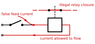
Double switching, double cutting, or double breaking is the practice of using a multipole switch to close or open both the positive and negative sides of a DC electrical circuit, or both the hot and neutral sides of an AC circuit. This technique is used to prevent shock hazard in electric devices connected with unpolarised AC power plugs and sockets. Double switching is a crucial safety engineering practice in railway signalling, wherein it is used to ensure that a single false feed of current to a relay is unlikely to cause a wrong-side failure. It is an example of using redundancy to increase safety and reduce the likelihood of failure, analogous to double insulation. Double switching increases the cost and complexity of systems in which it is employed, for example by extra relay contacts and extra relays, so the technique is applied selectively where it can provide a cost-effective safety improvement.
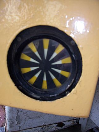
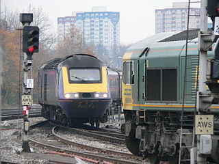
Automatic Warning System (AWS) is a railway safety system invented and predominantly used in the United Kingdom. It provides a train driver with an audible indication of whether the next signal they are approaching is clear or at caution. Depending on the upcoming signal state, the AWS will either produce a 'horn' sound, or a 'bell' sound. If the train driver fails to acknowledge a warning indication, an emergency brake application is initiated by the AWS. However if the driver correctly acknowledges the warning indication by pressing an acknowledgement button, then a visual 'sunflower' is displayed to the driver, as a reminder of the warning.

Cab signaling is a railway safety system that communicates track status and condition information to the cab, crew compartment or driver's compartment of a locomotive, railcar or multiple unit. The information is continually updated giving an easy to read display to the train driver or engine driver.

Centralized traffic control (CTC) is a form of railway signalling that originated in North America. CTC consolidates train routing decisions that were previously carried out by local signal operators or the train crews themselves. The system consists of a centralized train dispatcher's office that controls railroad interlockings and traffic flows in portions of the rail system designated as CTC territory. One hallmark of CTC is a control panel with a graphical depiction of the railroad. On this panel, the dispatcher can keep track of trains' locations across the territory that the dispatcher controls. Larger railroads may have multiple dispatcher's offices and even multiple dispatchers for each operating division. These offices are usually located near the busiest yards or stations, and their operational qualities can be compared to air traffic towers.
A wrong-side failure describes a failure condition in a piece of railway signalling equipment that results in an unsafe state. A typical example would be a signal showing a 'proceed' aspect when it should be showing a 'stop' or 'danger' aspect, resulting in a "false clear".

A rockfall or rock-fall is a quantity/sheets of rock that has fallen freely from a cliff face. The term is also used for collapse of rock from roof or walls of mine or quarry workings. "A rockfall is a fragment of rock detached by sliding, toppling, or falling, that falls along a vertical or sub-vertical cliff, proceeds down slope by bouncing and flying along ballistic trajectories or by rolling on talus or debris slopes."

A track circuit is an electrical device used to prove the absence of a train on rail tracks to signallers and control relevant signals. An alternative to track circuits are axle counters.

The railway signalling system used across the majority of the United Kingdom rail network uses lineside signals to control the movement and speed of trains.

The Pass of Brander stone signals, also known as Anderson's Piano, are a series of railway signals situated in the Pass of Brander, between Loch Awe and Taynuilt stations on the Oban branch of the West Highland Line in Scotland. A screen of wires, linked to semaphore signals, are erected on the mountainside alongside the railway. In the event of one or more wires being broken, signals in each direction are automatically placed at 'danger'. They are part of a warning system that advises train drivers to exercise caution in the event of a rock-fall, and cover a section of track that is just over 4 miles (6.4 km) in length.
The Charing Cross tube crash occurred at 08:32 hours on 10 March 1938, when a Northern line train ran into the rear of a stationary train near Charing Cross in London. Twelve people were slightly injured. The accident was caused by a signal technician carrying out a temporary repair to a faulty signal even though he was not familiar with the layout and did not have access to the signalling diagram.

The Continuous Automatic Warning System (CAWS) is a form of cab signalling and train protection system used in Ireland to help train drivers observe and obey lineside signals.

North American railroad signals generally fall into the category of multi-headed electrically lit units displaying speed-based or weak route signaling. Signals may be of the searchlight, color light, position light, or color position light types, each displaying a variety of aspects which inform the locomotive operator of track conditions so that they may keep their train under control and able to stop short of any obstruction or dangerous condition.

Railway semaphore signal is one of the earliest forms of fixed railway signals. This semaphore system involves signals that display their different indications to train drivers by changing the angle of inclination of a pivoted 'arm'. Semaphore signals were patented in the early 1840s by Joseph James Stevens, and soon became the most widely used form of mechanical signal. Designs have altered over the intervening years, and colour light signals have replaced semaphore signals in most countries, but in a few they remain in use.

Pulse code cab signaling is a form of cab signaling technology developed in the United States by the Union Switch and Signal corporation for the Pennsylvania Railroad in the 1920s. The 4-aspect system widely adopted by the PRR and its successor railroads has become the dominant railroad cab signaling system in North America with versions of the technology also being adopted in Europe and rapid transit systems. In its home territory on former PRR successor Conrail owned lines and on railroads operating under the NORAC Rulebook it is known simply as Cab Signaling System or CSS.

Roseville Tunnel is a 1,024-foot (312 m) two-track railroad tunnel on the Lackawanna Cut-Off in Byram Township, Sussex County, New Jersey. The tunnel is on a straight section of railroad between mileposts 51.6 and 51.8 (83 km), about 6 miles (9.7 km) north by northwest of Port Morris Junction. Operated for freight and passenger service from 1911 to 1979, it is undergoing work intended to return it to passenger service by 2026.


