
The unified modeling language (UML) is a general-purpose visual modeling language that is intended to provide a standard way to visualize the design of a system.
Model Driven Architecture (MDA) is a software design approach for the development of software systems. It provides a set of guidelines for the structuring of specifications, which are expressed as models. Model Driven Architecture is a kind of domain engineering, and supports model-driven engineering of software systems. It was launched by the Object Management Group (OMG) in 2001.
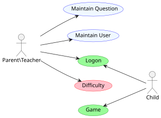
An actor in the Unified Modeling Language (UML) "specifies a role played by a user or any other system that interacts with the subject."

Model-based testing is an application of model-based design for designing and optionally also executing artifacts to perform software testing or system testing. Models can be used to represent the desired behavior of a system under test (SUT), or to represent testing strategies and a test environment. The picture on the right depicts the former approach.
A stereotype is one of three types of extensibility mechanisms in the Unified Modeling Language (UML), the other two being tags and constraints. They allow designers to extend the vocabulary of UML in order to create new model elements, derived from existing ones, but that have specific properties that are suitable for a particular domain or otherwise specialized usage. The nomenclature is derived from the original meaning of stereotype, used in printing. For example, when modeling a network you might need to have symbols for representing routers and hubs. By using stereotyped nodes you can make these things appear as primitive building blocks.

In software engineering, a sequence diagram shows process interactions arranged in time sequence. This diagram depicts the processes and objects involved and the sequence of messages exchanged as needed to carry out the functionality. Sequence diagrams are typically associated with use case realizations in the 4+1 architectural view model of the system under development. Sequence diagrams are sometimes called event diagrams or event scenarios.
The Data Distribution Service (DDS) for real-time systems is an Object Management Group (OMG) machine-to-machine standard that aims to enable dependable, high-performance, interoperable, real-time, scalable data exchanges using a publish–subscribe pattern.

In software engineering, a class diagram in the Unified Modeling Language (UML) is a type of static structure diagram that describes the structure of a system by showing the system's classes, their attributes, operations, and the relationships among objects.

Business Process Model and Notation (BPMN) is a graphical representation for specifying business processes in a business process model.

A deployment diagram "specifies constructs that can be used to define the execution architecture of systems and the assignment of software artifacts to system elements." To describe a web site, for example, a deployment diagram would show what hardware components ("nodes") exist, what software components ("artifacts") run on each node, and how the different pieces are connected.

A package diagram in the Unified Modeling Language depicts "specializations for Models and for Profiles that organize extensions to UML."

Activity diagrams are graphical representations of workflows of stepwise activities and actions with support for choice, iteration, and concurrency. In the Unified Modeling Language, activity diagrams are intended to model both computational and organizational processes, as well as the data flows intersecting with the related activities. "Object nodes hold data that is input to and output from executable nodes, and moves across object flow edges. Control nodes specify sequencing of executable nodes via control flow edges." In other words, although activity diagrams primarily show the overall control flow, they can also include elements showing the data flow between activities through one or more data stores.
Model-driven engineering (MDE) is a software development methodology that focuses on creating and exploiting domain models, which are conceptual models of all the topics related to a specific problem. Hence, it highlights and aims at abstract representations of the knowledge and activities that govern a particular application domain, rather than the computing concepts.
Executable UML is both a software development method and a highly abstract software language. It was described for the first time in 2002 in the book "Executable UML: A Foundation for Model-Driven Architecture". The language "combines a subset of the UML graphical notation with executable semantics and timing rules." The Executable UML method is the successor to the Shlaer–Mellor method.
Composite structure diagram in the Unified Modeling Language (UML) is a type of static structure diagram, that shows the internal structure of a class and the collaborations that this structure makes possible.
IBM App Connect Enterprise (abbreviated as IBM ACE, formerly known as IBM Integration Bus, WebSphere Message Broker, WebSphere Business Integration Message Broker, WebSphere MQSeries Integrator and started life as MQSeries Systems Integrator. App Connect IBM's integration software offering, allowing business information to flow between disparate applications across multiple hardware and software platforms. Rules can be applied to the data flowing through user-authored integrations to route and transform the information. The product can be used as an Enterprise Service Bus supplying a communication channel between applications and services in a service-oriented architecture. App Connect from V11 supports container native deployments with highly optimised container start-up times.

An artifact in the Unified Modeling Language (UML) is the "specification of a physical piece of information that is used or produced by a software development process, or by deployment and operation of a system."

A package in the Unified Modeling Language is used "to group elements, and to provide a namespace for the grouped elements". A package may contain other packages, thus providing for a hierarchical organization of packages.
UML state machine, formerly known as UML statechart, is an extension of the mathematical concept of a finite automaton in computer science applications as expressed in the Unified Modeling Language (UML) notation.
The Interaction Flow Modeling Language (IFML) is a standardized modeling language in the field of software engineering. IFML includes a set of graphic notations to create visual models of user interactions and front-end behavior in software systems.

