Adaptive biasing

Last updated

In magnetic tape recording, adaptive biasing is the technique of continuously varying the bias current to a recording head in accordance with the level of high-frequency audio signals. With adaptive biasing, high levels of high-frequency audio signals cause a proportionate decrease in bias current using either feedforward or preferably a negative feedback control system. Compared with the use of fixed bias current, adaptive biasing provides a higher maximum output level and higher dynamic range at the upper end of the audible spectrum and to a lesser extent, mid-range frequencies. The effect of adaptive biasing is most pronounced in compact cassette and low-speed reel-to-reel media. The first commercial implementation, the feedforward system Dolby HX was developed by Dolby Laboratories by 1979 and was rejected by the industry. The subsequent negative-feedback system Dolby HX Pro was developed by Bang & Olufsen and marketed by Dolby, and became the de facto standard of the consumer high fidelity industry in the mid-1980s.

Contents

Fixed and adaptive biasing

Simplified graphic explanation of the adaptive biasing principle. The shown magnetization curves (top) and bias control curve (bottom) are valid only at treble frequencies. The exact values of the breakpoints and slopes vary with frequency. Magnetization curve - adaptive biasing principle 03.svg
Simplified graphic explanation of the adaptive biasing principle. The shown magnetization curves (top) and bias control curve (bottom) are valid only at treble frequencies. The exact values of the breakpoints and slopes vary with frequency.

Tape bias is a strong, high-frequency, alternating current that is fed to a tape recording head along with the audio signal with the purpose of making more linear the inherently non-linear response of the magnetic particles in the tape's magnetic coating. [3] The frequency of the bias signal in consumer cassette decks is usually fixed at between 80 and 100 kHz. The quality of the bias signal is critical because noise, hum and direct current in the bias severely degrade audio fidelity. [4] The level of the bias signal defines the slope and shape of the resulting magnetization curve. [5]

The optimal bias level for each tape formulation is a compromise between maximum output levels, noise, distortion and frequency response. [6] [7] Nominal bias, corresponding to maximum sensitivity and/or maximum output at 10 kHz, is less desirable for mid-range frequencies. Over-biasing is better suited for mid-range and low frequencies but it reduces tape sensitivity at higher frequencies and degrades the signal-to-noise ratio. [8] [9] [10] As a side benefit, optimum bias improves the response to tape dropouts because stronger magnetic fields penetrate more deeply into the magnetic coating. [8] [9] [10] Under-biasing causes excessive distortion and modulation noise, and raises the susceptibility to dropouts, and is thus unwanted. [4] [10] In practice, tape is always slightly over biased; the optimal bias current is set at two or three decibels (dB) above the nominal value. [8] [9] [11] [10] This optimal setting improves linearity at mid-range frequencies but reduces dynamic range and causes a drop in high-frequency response, which is offset with pre-emphasis in the recording chain. [9] [11]

Recording very low wavelengths at tape speeds of 4.76 cm/s (1.87 in/s) and 9.53 cm/s (3.75 in/s) presents another challenge. [12] [4] Audible high-frequency components of the recorded signal act as biasing currents, resulting in excessive over-biasing that manifests itself in dynamic range compression and early onset of saturation at high frequencies, especially when recording on low quality tapes with low saturation levels. [4] [10] In the 1970s, music typically published on vinyl records or transmitted on FM radio did not contain much high-frequency energy and usually could not drive the tape into saturation. [11] The digitally mastered, direct-to-disc and disco recordings of the late 1970s and early 1980s, however, often contain enough high-frequency information, or "hot" treble, to trigger tape overload. [11]

In the late 1970s, the recording industry proposed three solutions to the problem. [13] Metal particle tapes had very high maximum output levels and treble saturation levels but were prohibitively expensive for most home users. [13] The early metal tapes had high absolute level of hiss and there were fears metal tape would quickly degrade [13] but this did not happen. The second solution was developed independently by Tandberg and Akai, and relied on limiting recording levels. [13] The patented Tandberg Dyneq and Akai ADRS circuits electronically compressed the signal before it could overload the tape. [13] In 1979, Kenneth James Gundry of Dolby Laboratories proposed the third alternative; adapting the bias current to the treble content of the source signal. [13] [11] The increase in high-frequency energy, which effectively overbiases the tape, would be compensated for with a reciprocal decrease in the output of the bias generator. [13]

The effect of such compensation is evident from the typical magnetization curves. [2] By default, when the source signal's treble energy is low, the recorder operates at a fixed optimal bias current Ib.opt. (blue curve). [2] Initial over-biasing assures good linearity but low sensitivity and low saturation levels. [2] Reduced bias current value of Ib.red. allows operation at higher input and output levels, albeit with a higher sensitivity (red curve). [2] [10] A well-designed adaptively biased circuit must gradually decrease bias current so the increase in sensitivity compensates for the saturation effects. [2] The new, adaptive magnetization curve remains straight (green dotted line) to the maximum recording current Iaf.1. [2] Owing to self-biasing effects, distortion at middle frequencies remains low and intermodulation decreases. [13]

The location of the breakpoint Iaf.o on the control curve and the slope of its high-level segment depend on the frequency of the input signal, and the energy-loss mechanisms in the tape and the recording head. [2] A practical adaptive-biasing system must employ heuristic weighing over the treble frequencies to attain the best performance of a specific recorder. [9] The effect of changes in tape formulations is insignificant in the case of ferric tapes. [9] Different tapes require different optimal bias settings but the bias control curve can be identical for all ferric tapes. [9]

Dolby HX

The original Dolby HX (for 'Headroom eXtension') designed by Gundry for Dolby Laboratories operated as an add-on to the Dolby B noise-reduction encoder. The Dolby B integrated circuit (IC) extracts the envelope of the mid-frequency and treble components of the source signals and uses it to modulate the gain of its side channel. [13] The HX circuit blends together the envelope signals of both stereo channels. [13] The composite envelope modulates the output of a voltage source that powers the common erase/bias generator, [13] thus varying the bias current. Simultaneously, the same envelope modulates the level of high-frequency pre-emphasis of the two recording channels. [13] Controlling both stereo channels with a single bias modulator was deemed acceptable due to the high degree of correlation between the left and right stereo signals, and the poor channel separation of the existing analog sources available to the consumer. [14] Controlling erase and bias currents simultaneously could cause sudden drops in the effectiveness of erasure but this only happened during the loudest passages with much treble content, which was sufficiently higher than any residual unerased signals to make these inaudible. [15]

Independent tests showed Dolby HX could raise the saturation levels at 10–12 kHz by 10 dB. [13] According to Dolby, the improvement was most pronounced with high quality, high coercivity tape formulations. Poor-quality tapes did not significantly respond to adaptive biasing. [16]

Dolby Laboratories launched Dolby HX at the Consumer Electronics Show in June 1979. [17] The system was offered to existing Dolby B licensees at no extra charge. [17] In 19801981, Aiwa, Harman Kardon and TEAC [18] integrated Dolby HX into their cassette decks but no other manufacturers followed suit. [19] Despite favorable reviews, Dolby HX was a marketing and an engineering failure. [19] It was tested and rejected by audio engineers; [19] while most did not disclose their findings, Willi Studer publicly spoke against the adoption of Dolby HX. [19] According to Studer, the shortcomings of Dolby HX greatly outweighed its intended benefits. [19] A 1981 press release by Dolby for the German market indirectly blamed the system's failure on conservatism in the industry. According to Dolby, Dolby HX "intervenes very far into recorder development and cannot simply be added to the existing electronics. It requires a fundamental redevelopment of the recording amplifier." [20] Dolby, however, still hoped Dolby HX would gain acceptance "because it enables high fidelity quality with the future microcassette recorders with a tape speed of 2.4 cm/s". [21] The latter promise did not materialize, either.

The main drawback of Dolby HX was that, being a feedforward control, it monitored the signal at its source but ignored the signal reaching the recording head. [14] [22] Variations in the gain or the frequency response of the recording chain disrupted the bias control curve. [14] The adjustable pre-emphasis sub-circuitry was unnecessarily complex and expensive for the consumer industry. [14] The Dolby B envelope detector, which by design was fairly slow, could not reliably track fast transients. [14] Bundling adaptive biasing with noise reduction at the hardware level was the worst of all shortcomings. [14] The user could not turn off the Dolby B decoder and still use Dolby HX while recording. [23] This discouraged the use of the more effective dbx noise reduction. [23] The 30 dB gain in signal-to-noise ratio provided by dbx made Dolby HX virtually unnecessary. [23]

Dolby HX Pro

The complete Dolby HX circuitry built around the NEC mPC1297, made in 1989. The shown implementation is a rare example of a defeatable HX Pro, controlled with a user-accessible on/off switch. Marantz SD-60 main audio PCB - NEC uPC1297 Dolby HX Pro IC.jpg
The complete Dolby HX circuitry built around the NEC μPC1297, made in 1989. The shown implementation is a rare example of a defeatable HX Pro, controlled with a user-accessible on/off switch.

In 1980, an alternative implementation of adaptive biasing was patented by Jørgen Selmer Jensen of Bang & Olufsen (B&O). [24] Unlike the feedforward Dolby HX, the B&O circuit was a feedback system. [22] According to the patent, it monitored the high-frequency voltage at the "hot" end of the recording head, extracting the combined envelope of bias and treble audio signals. [24] [22] An error amplifier continuously compared the envelope with the preset reference level and adjusted the bias current being fed to the recording head [22] via a resistive opto-isolator. [24] [lower-alpha 1] The monaural circuit was easily scalable for stereophonic and multitrack recording, and enabled easy adjustments of the normal bias level. [24]

According to B&O, its system assured only 3-5 dB gain in treble saturation, far less than Dolby HX. [14] B&O's system did not rely on the Dolby IC and could be used with or without any noise reduction system. [14] Negative feedback compensated for variations in gain and frequency response in the recording chain, eliminating the key shortcoming of Dolby HX. [14] As a side benefit, the B&O system was also effective in reel-to-reel recorders. [14] [25]

Dolby Laboratories acquired the rights to the B&O patent and became its sole worldwide distributor. [22] The new system was named Dolby HX Professional, which was later shortened to Dolby HX Pro. B&O retained the rights to use Dolby HX Pro in its products and, according to sources affiliated with Selmer, received a share of future licensing revenue. [26]

At its launch, Dolby targeted HX Pro at professional markets. [14] In August 1982, industrial tape duplicator manufacturer Electro Sound introduced HX Pro into its cassette-duplicator catalogue. [27] Warner Records became the first major recording label to adopt HX Pro for mass duplication. [28] By February 1983, according to Dolby, the company had two licensees in the home audio industry; Aiwa and Harman Kardon. [29] The early adopters had to build Dolby HX Pro circuitry with general-purpose operational amplifiers and transconductance amplifiers until the 1985 introduction of a dedicated IC, the NEC μPC1297. [30] The new proposal was well received by the industry and by 1986, Dolby HX Pro became a standard feature in the upper segment of consumer cassette decks. [28] In the following years, Dolby HX Pro migrated into the entry-level consumer segment, becoming the de facto standard equipment in consumer hi-fi, and was also integrated into professional reel-to-reel recorders. [25]

Subsequent development

In 1983, adaptive biasing gained popularity in the Soviet Union. The earliest implementation, published by Nikolay Sukhov, was developed after Dolby HX Pro. It blended the elements of HX Pro (feedback control) and Dolby HX, varying the supply voltage to the common erase/bias generator, and added safeguards against transient overload, a common problem when recording from worn LP records. [14] The revised design, which used a new precision rectifier IC, was published in 1987. [9]

In line with the tastes of the home audio community, which still preferred reel-to-reel tapes to cassettes, the 1987 version was targeted at cassette decks and reel-to-reel decks. [9] Adaptive biasing cannot substantially improve the performance of one-quarter-inch (0.64 cm) tape running at 19.5 cm/s (7.5 in/s) or higher speeds in standard reel-to-reel recorders; its saturation envelope is suitably high for music signals. Adaptive biasing, however, permits a decrease in treble equalization from the standard 50 μs to 10 μs. [9] A fivefold reduction of the time constant corresponds to a fivefold decrease in apparent noise floor at middle and treble frequencies. According to Sukhov, his system enables a practical signal-to-noise ratio of more than 80 dB, without noise reduction. [9] Sukhov's designs were the subject of five patents issued between 1984 and 1989, all of which referenced the earlier Selmer patent as prior art. [31] [32] [33] [34] [35]

Footnotes

  1. In practical applications the latter were replaced with variable-gain amplifiers, for example, built around the LM13700 transconductance amplifier). [22]

Notes

  1. Sukhov 1987, p. 40, fig. 1-2.
  2. 1 2 3 4 5 6 7 8 Sukhov 1987, pp. 39–40.
  3. Watkinson 1998, p. 310.
  4. 1 2 3 4 Watkinson 1998, p. 312.
  5. Watkinson 1998, pp. 310–312.
  6. Watkinson 1998, pp. 312–313.
  7. Dolby 1981, p. 270.
  8. 1 2 3 Watkinson 1998, p. 313.
  9. 1 2 3 4 5 6 7 8 9 10 11 Sukhov 1987, p. 40.
  10. 1 2 3 4 5 6 Dolby 1981, p. 269.
  11. 1 2 3 4 5 Stark, Craig (1982). "The Dolby HX System" (PDF) (Tape Recording and Buying Guide): 18.{{cite journal}}: Cite journal requires |journal= (help)
  12. Sukhov 1983, p. 36.
  13. 1 2 3 4 5 6 7 8 9 10 11 12 13 Sukhov 1983, p. 37.
  14. 1 2 3 4 5 6 7 8 9 10 11 12 Sukhov 1983, p. 38.
  15. Sukhov 1983, p. 39.
  16. Dolby 1981, p. 271: "Schlechte Bänder bleiben schlecht".
  17. 1 2 "Engineers sound off to high frequencies". New Scientist (21 Jun): 999. 1979.
  18. "Teac decks and test tapes" (PDF). Modern Recording and Music (9): 31. 1980.
  19. 1 2 3 4 5 Sukhov 1983, p. 40.
  20. Dolby 1981, p. 269: "Eine technische Begründung für die spärliche Verbreitung des HX-Systems ist darin zu sehen, das es sehr weit in die Recorderentwicklung eingreift, und sich nicht einfach zu der vorhandenen Elektronik hinzufügen läßt. Dolby-HX erfordert eine grundlegende Neuentwicklung der Aufnahmeverstärker".
  21. Dolby 1981, p. 269: "Dennoch stehen die Chancen für das HX-System nicht schlecht, weil es bei den kommenden (Mikro)-Cassettenrecordern mit 2,4 cm/s Bandgeschwindigkeit HiFi-Qualität ermöglicht.".
  22. 1 2 3 4 5 6 Self 2020, p. 56.
  23. 1 2 3 Burstein, H. (1983). "Tape guide: Doubling in NR" (PDF). Audio (USA) (February): 26.
  24. 1 2 3 4 EP 0046410,Jensen, Jorgen Selmer,"Bias control method and apparatus for magnetic recording",published 1982-02-24, assigned to Bang & Olufsen A/S
  25. 1 2 Hood 1999, p. 45.
  26. "Jørgen Selmer Jensen". 2013. Archived from the original on 14 September 2013.
  27. "New Products / Dolby HX". Billboard. 1982-08-28. p. 31.
  28. 1 2 Shea, T. (1986). "Rx for tapes: HX Pro". Popular Mechanics (August): 34–35.
  29. Dolby Laboratories (1983). "Dolby HX Professional" (PDF). Audio (USA) (February): 7.
  30. "NEC IC Expands Bias in Audio Tape Heads". Journal of Electronic Engineering. 22: 19. 1985.
  31. SU 1448356,Sukhov, Nikolaj Evgenyevich,"Magnetic recording apparatus with dynamic magnetizing",published 1988-12-30
  32. SU 1448357,Sukhov, Nikolaj Evgenyevich,"Method of magnetic recording with dynamic magnetizing",published 1988-12-30
  33. SU 1531134,Sukhov, Nikolaj Evgenyevich,"Device for magnetic recording with dynamic biasing",published 1989-12-23
  34. SU 1539830,Sukhov, Nikolaj Evgenyevich,"Device for magnetic recording with adaptive magnetizing",published 1990-01-30
  35. SU 1610487,Sukhov, Nikolaj Evgenyevich,"Device for magnetic recording with dynamic bias",published 1990-11-30

Related Research Articles

<span class="mw-page-title-main">Tape bias</span> Technique that improves the fidelity of analogue tape recorders

Tape bias is the term for two techniques, AC bias and DC bias, that improve the fidelity of analogue tape recorders. DC bias is the addition of direct current to the audio signal that is being recorded. AC bias is the addition of an inaudible high-frequency signal to the audio signal. Most contemporary tape recorders use AC bias.

Dynamic range is the ratio between the largest and smallest values that a certain quantity can assume. It is often used in the context of signals, like sound and light. It is measured either as a ratio or as a base-10 (decibel) or base-2 logarithmic value of the difference between the smallest and largest signal values.

<span class="mw-page-title-main">Emphasis (telecommunications)</span> Process of boosting noise-prone parts of the signal before transmission (and reversing upon receipt)

In signal processing, pre-emphasis is a technique to protect against anticipated noise. The idea is to boost the frequency range that is most susceptible to noise beforehand, so that after a noisy process more information can be recovered from that frequency range. Removal of the distortion caused by pre-emphasis is called de-emphasis, making the output accurately reproduce the original input.

<span class="mw-page-title-main">Cassette tape</span> Magnetic audio tape recording format

The Compact Cassette, also commonly called a cassette tape, audio cassette, or simply tape or cassette, is an analog magnetic tape recording format for audio recording and playback. Invented by Lou Ottens and his team at the Dutch company Philips in 1963, Compact Cassettes come in two forms, either containing content as a prerecorded cassette (Musicassette), or as a fully recordable "blank" cassette. Both forms have two sides and are reversible by the user. Although other tape cassette formats have also existed—for example the Microcassette—the generic term cassette tape is normally used to refer to the Compact Cassette because of its ubiquity.

<span class="mw-page-title-main">Tape recorder</span> Machine for recording sound

An audio tape recorder, also known as a tape deck, tape player or tape machine or simply a tape recorder, is a sound recording and reproduction device that records and plays back sounds usually using magnetic tape for storage. In its present-day form, it records a fluctuating signal by moving the tape across a tape head that polarizes the magnetic domains in the tape in proportion to the audio signal. Tape-recording devices include the reel-to-reel tape deck and the cassette deck, which uses a cassette for storage.

<span class="mw-page-title-main">Dolby noise-reduction system</span> A line of noise reduction systems for reel-to-reel and cassette tape recorders

A Dolby noise-reduction system, or Dolby NR, is one of a series of noise reduction systems developed by Dolby Laboratories for use in analog audio tape recording. The first was Dolby A, a professional broadband noise reduction system for recording studios in 1965, but the best-known is Dolby B, a sliding band system for the consumer market, which helped make high fidelity practical on cassette tapes, which used a relatively noisy tape size and speed. It is common on high-fidelity stereo tape players and recorders to the present day, although Dolby has as of 2016 ceased licensing the technology for new cassette decks. Of the noise reduction systems, Dolby A and Dolby SR were developed for professional use. Dolby B, C, and S were designed for the consumer market. Aside from Dolby HX, all the Dolby variants work by companding: compressing the dynamic range of the sound during recording, and expanding it during playback.

A cassette deck is a type of tape machine for playing and recording audio cassettes that does not have a built-in power amplifier or speakers, and serves primarily as a transport. It can be a part of an automotive entertainment system, a part of a portable mini system or a part of a home component system. In the latter case it is also called a component cassette deck or just a component deck.

Sound can be recorded and stored and played using either digital or analog techniques. Both techniques introduce errors and distortions in the sound, and these methods can be systematically compared. Musicians and listeners have argued over the superiority of digital versus analog sound recordings. Arguments for analog systems include the absence of fundamental error mechanisms which are present in digital audio systems, including aliasing and associated anti-aliasing filter implementation, jitter and quantization noise. Advocates of digital point to the high levels of performance possible with digital audio, including excellent linearity in the audible band and low levels of noise and distortion.

<span class="mw-page-title-main">Reel-to-reel audio tape recording</span> Audio recording using magnetic tape spooled on open reels

Reel-to-reel audio tape recording, also called open-reel recording, is magnetic tape audio recording in which the recording tape is spooled between reels. To prepare for use, the supply reel containing the tape is placed on a spindle or hub. The end of the tape is manually pulled from the reel, threaded through mechanical guides and over a tape head assembly, and attached by friction to the hub of the second, initially empty takeup reel. Reel-to-reel systems use tape that is 1412, 1, or 2 inches wide, which normally moves at 3+347+12, 15 or 30 inches per second. Domestic consumer machines almost always used 14 inch (6.35 mm) or narrower tape and many offered slower speeds such as 1+78 inches per second (4.762 cm/s). All standard tape speeds are derived as a binary submultiple of 30 inches per second.

Nakamichi Corp., Ltd. is a Japanese consumer electronics brand that originated in Japan and gained a name from the 1970s onwards for innovative and high quality audio cassette decks. Nakamichi is a subsidiary of Chinese holding company Nimble Holdings.

Print-through is a generally undesirable effect that arises in the use of magnetic tape for storing analog information, in particular music, caused by contact transfer of signal patterns from one layer of tape to another as it sits wound concentrically on a reel.

dbx (noise reduction) Family of noise reduction systems

dbx is a family of noise reduction systems developed by the company of the same name. The most common implementations are dbx Type I and dbx Type II for analog tape recording and, less commonly, vinyl LPs. A separate implementation, known as dbx-TV, is part of the MTS system used to provide stereo sound to North American and certain other TV systems. The company, dbx, Inc., was also involved with Dynamic Noise Reduction (DNR) systems.

Noise reduction is the process of removing noise from a signal. Noise reduction techniques exist for audio and images. Noise reduction algorithms may distort the signal to some degree. Noise rejection is the ability of a circuit to isolate an undesired signal component from the desired signal component, as with common-mode rejection ratio.

<span class="mw-page-title-main">Tape head</span> Component used to read magnetic tape

A tape head is a type of transducer used in tape recorders to convert electrical signals to magnetic fluctuations and vice versa. They can also be used to read credit/debit/gift cards because the strip of magnetic tape on the back of a credit card stores data the same way that other magnetic tapes do. Cassettes, reel-to-reel tapes, 8-tracks, VHS tapes, and even floppy disks and early hard drive disks all use the same principle of physics to store and read back information. The medium is magnetized in a pattern. It then moves at a constant speed over an electromagnet. Since the moving tape is carrying a changing magnetic field with it, it induces a varying voltage across the head. That voltage can then be amplified and connected to speakers in the case of audio, or measured and sorted into ones and zeroes in the case of digital data.

<span class="mw-page-title-main">Sound recording and reproduction</span> Recording of sound and playing it back

Sound recording and reproduction is the electrical, mechanical, electronic, or digital inscription and re-creation of sound waves, such as spoken voice, singing, instrumental music, or sound effects. The two main classes of sound recording technology are analog recording and digital recording.

The history of sound recording - which has progressed in waves, driven by the invention and commercial introduction of new technologies — can be roughly divided into four main periods:

<span class="mw-page-title-main">Chromium(IV) oxide</span> Chemical compound

Chromium dioxide or chromium(IV) oxide is an inorganic compound with the formula CrO2. It is a black synthetic magnetic solid. It once was widely used in magnetic tape emulsion. With the increasing popularity of CDs and DVDs, the use of chromium(IV) oxide has declined. However, it is still used in data tape applications for enterprise-class storage systems. It is still considered by many oxide and tape manufacturers to have been one of the best magnetic recording particulates ever invented.

<span class="mw-page-title-main">Nakamichi Dragon</span> High end hifi cassette deck

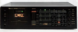
The Nakamichi Dragon is an audio cassette deck that was introduced by Nakamichi in 1982 and marketed until 1994. The Dragon was the first Nakamichi model with bidirectional replay capability and the world's first production tape recorder with an automatic azimuth correction system; this feature, which was invented by Philips engineers and improved by Niro Nakamichi, continuously adjusts the azimuth of the replay head to minimize apparent head skew and correctly reproduce the treble signal present on the tape. The system allows the correct reproduction of mechanically skewed cassettes and recordings made on misaligned decks. Apart from the Dragon, similar systems have only been used in the Nakamichi TD-1200 car cassette player and the Marantz SD-930 cassette deck.

<span class="mw-page-title-main">Compact Cassette tape types and formulations</span>

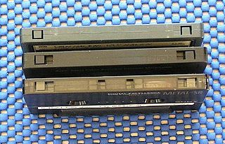
Audio compact cassettes use magnetic tape of three major types which differ in fundamental magnetic properties, the level of bias applied during recording, and the optimal time constant of replay equalization. Specifications of each type were set in 1979 by the International Electrotechnical Commission (IEC): Type I, Type II, Type III, and Type IV. 'Type 0' was a non-standard designation for early compact cassettes that did not conform to IEC specification.

<span class="mw-page-title-main">Revox B215</span> Cassette deck manufactured from 1985–1990

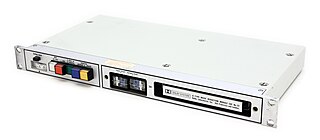
The Revox B215 is a cassette deck manufactured by Studer from 1985 until around 1990. A professional version with different control layout and audio path electronics was manufactured concurrently as the Studer A721. A later improved version was marketed as the Revox B215S. Because it was expensive compared to other consumer models and had exceptionally good mechanical performance and durability, the B215 was used primarily by professional customers—radio stations, recording studios and real-time cassette duplicators.

References

In English

In German

In Russian