Explorer 2

Last updated

Explorer 2
Juno-1 explorer-2.jpg
Launch of Explorer 2 satellite
NamesExplorer II
Mission type Earth science
Operator JPL / Army Ballistic Missile Agency
Mission durationFailed to orbit
120 days (planned)
Spacecraft properties
SpacecraftExplorer II
Spacecraft typeScience Explorer
Bus Explorer 1
Manufacturer Jet Propulsion Laboratory
Launch mass14.22 kg (31.3 lb)
Dimensions203 cm (80 in) length
15.2 cm (6.0 in) diameter
Power60 watts
Start of mission
Launch date5 March 1958, 18:27:57 GMT [1]
Rocket Juno I (RS-26)
Launch site Atlantic Missile Range, LC-26A
Contractor Army Ballistic Missile Agency
End of mission
DestroyedFailed to orbit
Orbital parameters
Reference system Geocentric orbit (planned) [2]
Regime Medium Earth orbit
Perigee altitude 358 km (222 mi)
Apogee altitude 2,550 km (1,580 mi)
Inclination 32.24°
Period 114.80 minutes
Instruments
Geiger counter
Micrometeorite Detector
Satellite Drag Atmospheric Density
Resistance Thermometers
Thermometers
Explorer program
 

Explorer 2 was an American unmanned space mission within the Explorer program. Intended to be a repetition of the previous Explorer 1 mission, which placed a satellite into medium Earth orbit, the spacecraft was unable to reach orbit due to a failure in the launch vehicle during launch.

Contents

Explorer 2 was launched from Cape Canaveral Missile Test Center of the Atlantic Missile Range (AMR), LC-26A in Florida on 5 March 1958 at 18:27:57 GMT by a Juno I launch vehicle. [3] The Juno I had its origins in the United States Army's Project Orbiter in 1954. The project was canceled in 1955 when the decision was made to proceed with Project Vanguard.

Background

Following the launch of the Soviet Sputnik 1 on 4 October 1957, the Army Ballistic Missile Agency (ABMA) was directed to proceed with the launching of a satellite using the Juno I four-stage variant of the three-stage Jupiter-C, which had already been flight-tested in nose-cone re-entry tests for the Jupiter IRBM (intermediate-range ballistic missile). Working closely together, ABMA and Jet Propulsion Laboratory (JPL) completed the job of modifying the Jupiter-C and building Explorer 1 in 84 days.

Spacecraft

Explorer 2 was identical to Explorer 1 except for the addition of a tape recorder designed to enable playback of data. The satellite was a 203 cm (80 in) long, 15.2 cm (6.0 in) diameter cylinder and nosecone that comprised the fourth stage of the Jupiter-C launch vehicle. With a mass of 14.22 kg (31.3 lb), it was about 0.25 kg (0.55 lb) heavier than Explorer 1. The spacecraft body was made of stainless AISI-410 steel, 0.058 cm (0.023 in) thick. The case was heat-oxidized to a gold color and eight alternate stripes of white Rokide A (flame sprayed aluminum oxide) were used for temperature control. [4]

The base of the cylinder held the Sergeant solid-fuel rocket motor. The sub-carrier oscillators and Mallory mercury batteries for the low power transmitter were in the upper part of the nose cone. Below these was the low power (10 mW, 108.00 MHz) transmitter for the carrier and sub-carrier signals, which used the stainless steel satellite skin as a dipole antenna. [4]

Below the nose cone was the detector deck, holding the Geiger-Mueller counter tube for the cosmic ray experiment, the command receiver, for recorder interrogations, high power playback transmitter (60 mW, 108.03 MHz) for interrogation response, cosmic ray experiment electronics, Mallory mercury batteries for the high power transmitter, and a 0.23 kg (0.51 lb), 5.7 cm (2.2 in) diameter magnetic tape recorder. An acoustic micrometeorite detector was mounted to the inside of the spacecraft cylinder near the cosmic ray device. Near the bottom of the detector deck four circularly polarized turnstile stainless steel wire whip antennas protruded radially from the side of the spacecraft, equally spaced around the axis. A gap for the high powered antenna and a heat radiation shield were between the payload and the rocket motor. The micrometeorite detectors were arranged in a ring around the cylinder near the bottom of the spacecraft. Four temperature gauges were mounted a various locations in the spacecraft. [4]

Explorer 2 was equipped with a Geiger counter for the purposes of detecting cosmic rays. After Explorer 3, it was decided that the original Geiger counter had been overwhelmed by strong radiation coming from a belt of charged particles trapped in space by the Earth's magnetic field (see: Van Allen radiation belt). Explorer 2 was also equipped with a wire grid array and an acoustic detector for the purpose of micrometeorite detection.

Instruments

Geiger counter

An Anton 314 omnidirectional Geiger tube detector was used to measure the flux of energetic charged particles (protons E>30 MeV and electrons E>3 MeV). The instrument consisted of a single Geiger-Mueller tube, a scaling circuit to reduce the number of pulses, and a telemetry system to transmit the data to ground receiving stations. The Geiger-Mueller tube was a type 314 Anton halogen quenched counter with stainless steel (approximately 75% iron, 25% chromium) wall of approximately 0.12 cm (0.047 in) thickness. The instrument was mounted within the spacecraft hull, which had 0.58 mm (0.023 in) thick stainless steel walls. The counter was 10.2 cm (4.0 in) long by 2.0 cm (0.79 in) diameter and the internal wire was 10 cm (3.9 in) in length. The tube had a very small variation in counting efficiency over the range -55° to +175° Celsius. It had approximately 85% counting efficiency for cosmic rays, and about 0.3% counting efficiency for photons of energy 660 keV. The "dead time" (time to reset to record the next count) of the counters was about 100 microseconds. The counter was connected to a current amplifier, which directly fed a scaler stage, a bistable transistor multivibrator that could operate over a wide range of voltages and a temperature range of -15° to +85°Celsius, limited primarily by the supply batteries. The scaler resolving time was 250 microseconds. For pulse counts higher than 4000 per second, the scaler indicated a count of 4000. Results were sent to the ground through the telemetry system in real time. The experiment had no onboard data storage device, and could only send telemetry to the ground when it was passing over an Earth receiving station, so some regions had no coverage during the flight. [5]

Micrometeorite Detector

Direct measurements of micrometeorites were made on Explorer 1 using two separate detectors: a wire grid detector and a crystal transducer. The parameters determined were the influx rates of each size interval, the impinging velocity, the composition, and the density of the micrometeorite. [6]

The wire grid detector consisted of 12 cards (connected in parallel) mounted in a fiberglass supporting ring which in turn was mounted on the satellite's cylindrical surface. Each card was wound with enameled 17-micron-diameter nickel alloy wire. Two layers of wire were wound on each card to ensure that a total area of 1 × 1 cm (0.39 × 0.39 in) completely covered. A micrometeorite of about 10 microns would fracture the wire upon impact, destroy the electrical connection, and thus record the event. [6]

The acoustic detector (transducer and solid-state amplifier) was placed in acoustical contact with the middle section skin where it could respond to meteorite impacts on the spacecraft skin such that each recorded event would be a function of mass and velocity. The effective area of this section was 0.075 m2, and the average threshold sensitivity was 0.0025 g-cm/s. [6]

Satellite Drag Atmospheric Density

Because of its symmetrical shape, Explorer 2 was selected for use in determining upper atmospheric densities as a function of altitude, latitude, season, and solar activity. Density values near perigee were deduced from sequential observations of the spacecraft position, using optical (Baker-Nunn camera network) and radio and/or radar tracking techniques. [7]

Resistance Thermometers

The Explorer 2 satellite was equipped with four resistance thermometers that made direct temperature measurements, three external and one internal. The primary purpose of the experiment was to study the efficacy of passive thermal control (in this case, insulation and exterior coatings) on the exterior and interior of a satellite, and to document the temperature of the instrumentation to study its effect on instrument operation. [8]

Thermometers

The thermometer designated external temperature gauge no. 1 was mounted on the outer hull at the bottom of the upper (instrumentation) section of the satellite. This measured the cylinder skin temperature over a range of -50°C to +110°C, with an accuracy of 4°C over the range -10°C to +80°C. External temperature gauge no. 2 was mounted along the bottom of the nose cone to measure the nose cone skin temperature. It could cover a range of -50°C to +220°C. The accuracy was 16°C at a temperature of 50°C and 18°C at 0°C. External temperature gauge no. 3 was mounted at the top of the nose cone and measured the stagnation-point temperature. It covered from -50°C to +450°C with an accuracy of approximately 20°C. [8]

The internal temperature gauge was mounted in the high powered transmitter at the base of the instrumentation section. It could cover a range of -60°C to +110°C. The accuracy was 2°C at temperatures from 0°C to +30°C and fell off to an accuracy of 20°C at a temperature of 90°C. External temperature gauges no. 2 and no. 3 transmitted on the low-powered (10 mW, 108.00-MHz) transmitter, and the other two gauges transmitted on the high-powered (60 mW, 108.03-MHz) transmitter. Additionally, the nose cone internal temperature could be indirectly estimated by measuring the frequency of the cosmic ray channel. Calibrations of the oscillator indicate the internal nose cone temperature could be known within 12°C from 0 to +25°C, and to 6°C for 25 to 50°C. [8]

Telemetry

The telemetry was broadcast continuously. There were no recorders or data storage devices on board, so temperature data could only be received in real time covering periods when Explorer 1 was over a receiving station. There were 5 receiving stations: Patrick Air Force Base (Cape Canaveral), Earthquake Valley (near San Diego), San Gabriel, California, Singapore (Malaya), and Ibadan (Nigeria). All 5 could receive data from the low-power transmitter, only Patrick AFB and San Gabriel could receive from the high-power transmitter. There were typically 4 passes per day over Patrick AFB, Earthquake Valley, and San Gabriel, and 7 passes per day over Nigeria and Singapore. [8]

Thermal control

The exterior temperature control was achieved by coating a fraction of the stainless steel satellite casing with an aluminum oxide ceramic (Rokide A). Approximately 30% of the nose cone (upper 30 cm of the satellite) and 25% of the upper 51.4 cm (20.2 in) of the cylindrical body were coated in longitudinal stripes. There was insulation between the nose cone and instrument compartment, and between the instrument compartment and rocket motor section. [8]

An internal temperature range of -5°C to +45°C was required for proper operation of the equipment in the satellite. The batteries would not operate below -5°C, but low temperatures would not damage the batteries or equipment. Permanent damage to the equipment would not occur unless the temperature rose above +80°C. [8]

Telecommunications

Data were continuously transmitted using a 60 mW amplitude-modulated transmitter and a 10 mW phase-modulated transmitter, both transmitting as a frequency of 108 MHz. Data were recorded only when the spacecraft was over one of seventeen receiving stations. Both the high-power and low-power transmitters were battery powered and operated. [9]

Launch vehicle

The launch vehicle was a Juno I, a variant of the three-stage Jupiter-C with an added fourth propulsive stage, which in this case was the Explorer 2. The first stage was an upgraded Redstone liquid-fueled launch vehicle. The second stage comprised a cluster of eleven Sergeant solid-fuel rocket motors and the third stage held three Sergeants. The booster was equipped to spin the fourth stage in increments, leading to a final rate of 750 rpm about its long axis. [4]

Mission

Explorer 2 launched from the Cape Canaveral Missile Test Center of the Atlantic Missile Range (AMR), pad 26A, on 5 March 1958 at 18:27:57 GMT. [1] The flight was nominal through third stage ignition. The fourth stage failed to ignite, making attainment of orbital velocity impossible. The spacecraft reentered the atmosphere and fell into the Atlantic Ocean near Trinidad, some 3,000 km (1,900 mi) from the launch site. The cause of the failure was believed to be due to failure of a light plastic cone, which held the igniter in place at the fourth stage nozzle, under the launch stresses. This allowed the igniter to fall out of position. The igniter support was strengthened for later flights. [4] [10]

See also

Related Research Articles

<span class="mw-page-title-main">Explorer 1</span> First satellite launched by the United States (1958)

Explorer 1 was the first satellite launched by the United States in 1958 and was part of the U.S. participation in the International Geophysical Year (IGY). The mission followed the first two satellites, both launched by the Soviet Union during the previous year, Sputnik 1 and Sputnik 2. This began a Space Race during the Cold War between the two nations.

<span class="mw-page-title-main">Pioneer 3</span> NASA robotic spacecraft designed to study the Moon

Pioneer 3 was a spin-stabilized spacecraft launched at 05:45:12 GMT on 6 December 1958 by the U.S. Army Ballistic Missile Agency in conjunction with NASA, using a Juno II rocket. This spacecraft was intended as a lunar probe, but failed to go past the Moon and into a heliocentric orbit as planned. It did however reach an altitude of 102,360 km before falling back to Earth. The revised spacecraft objectives were to measure radiation in the outer Van Allen radiation belt using two Geiger-Müller tubes and to test the trigger mechanism for a lunar photographic experiment.

<span class="mw-page-title-main">Pioneer 4</span> NASA robotic spacecraft designed to study the Moon

Pioneer 4 was an American spin-stabilized uncrewed spacecraft launched as part of the Pioneer program on a lunar flyby trajectory and into a heliocentric orbit making it the first probe of the United States to escape from the Earth's gravity. Launched on March 3, 1959, it carried a payload similar to Pioneer 3: a lunar radiation environment experiment using a Geiger–Müller tube detector and a lunar photography experiment. It passed within 58,983 km (36,650 mi) of the Moon's surface. However, Pioneer 4 did not come close enough to trigger its photoelectric sensor. The spacecraft was still in solar orbit as of 1969. It was the only successful lunar probe launched by the U.S. in 12 attempts between 1958 and 1963; only in 1964 would Ranger 7 surpass its success by accomplishing all of its mission objectives.

<span class="mw-page-title-main">Explorer 4</span> Satellite launched by the United States (1958)

Explorer 4 was an American satellite launched on 26 July 1958. It was instrumented by Dr. James van Allen's group. The Department of Defense's Advanced Research Projects Agency (ARPA) had initially planned two satellites for the purposes of studying the Van Allen radiation belts and the effects of nuclear explosions upon these belts, however Explorer 4 was the only such satellite launched as the other, Explorer 5, suffered launch failure.

<span class="mw-page-title-main">Vanguard 3</span>

Vanguard 3 is a scientific satellite that was launched into Earth orbit by the Vanguard SLV-7 on 18 September 1959, the third successful Vanguard launch out of eleven attempts. Vanguard rocket: Vanguard Satellite Launch Vehicle-7 (SLV-7) was an unused Vanguard TV-4BU rocket, updated to the final production Satellite Launch Vehicle (SLV).

Explorer 3 was an American artificial satellite launched into medium Earth orbit in 1958. It was the second successful launch in the Explorer program, and was nearly identical to the first U.S. satellite Explorer 1 in its design and mission.

<span class="mw-page-title-main">Explorer 35</span> NASA satellite of the Explorer program

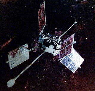
Explorer 35,, was a spin-stabilized spacecraft built by NASA as part of the Explorer program. It was designed for the study of the interplanetary plasma, magnetic field, energetic particles, and solar X-rays, from lunar orbit.

<span class="mw-page-title-main">Explorer 6</span> NASA satellite of the Explorer program

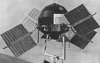
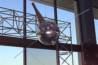
Explorer 6, or S-2, was a NASA satellite, launched on 7 August 1959, at 14:24:20 GMT. It was a small, spheroidal satellite designed to study trapped radiation of various energies, galactic cosmic rays, geomagnetism, radio propagation in the upper atmosphere, and the flux of micrometeorites. It also tested a scanning device designed for photographing the Earth's cloud cover. On 14 August 1959, Explorer 6 took the first photos of Earth from a satellite.

<span class="mw-page-title-main">Explorer 11</span> NASA satellite of the Explorer program

Explorer 11 was a NASA satellite that carried the first space-borne gamma-ray telescope. This marked the beginning of space gamma-ray astronomy. Launched on 27 April 1961 by a Juno II, the satellite returned data until 17 November 1961, when power supply problems ended the science mission. During the spacecraft's seven-month lifespan it detected twenty-two events from gamma-rays and approximately 22,000 events from cosmic radiation.

<span class="mw-page-title-main">Explorer 7</span> NASA satellite of the Explorer program

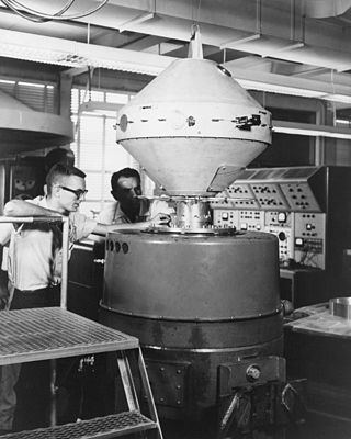
Explorer 7 was a NASA satellite launched on 13 October 1959, at 15:30:04 GMT, by a Juno II launch vehicle from Cape Canaveral Air Force Station (CCAFS) to an orbit of 573 × 1,073 km (356 × 667 mi) and inclination of 50.27°. It was designed to measure solar X-ray and Lyman-alpha flux, trapped energetic particles, and heavy primary cosmic rays. Secondary objectives included collecting data on micrometeoroid penetration, molecular sputtering and studying the Earth-atmosphere heat balance.

<span class="mw-page-title-main">Explorer 5</span> United States satellite launched in 1958

Explorer 5 was a United States satellite with a mass of 17.43 kg (38.4 lb). It was the last of the original series of Explorer satellites built, designed, and operated by the Jet Propulsion Laboratory.

<span class="mw-page-title-main">Explorer 8</span> NASA satellite of the Explorer program

Explorer 8 was a NASA research satellite launched on 3 November 1960. It was intended to study the temporal and spatial distribution of the electron density, the electron temperature, the ion concentration, the ion mass, the micrometeorite distribution, and the micrometeorite mass in the ionosphere at altitudes between 400 km (250 mi) and 1,600 km (990 mi) and their variation from full sunlit conditions to full shadow, or nighttime, conditions.

<span class="mw-page-title-main">Explorer 18</span> NASA satellite of the Explorer program

Explorer 18, also called IMP-A, IMP-1, Interplanetary Monitoring Platform-1 and S-74, was a NASA satellite launched as part of the Explorer program. Explorer 18 was launched on 27 November 1963 from Cape Canaveral Air Force Station (CCAFS), Florida, with a Thor-Delta C launch vehicle. Explorer 18 was the first satellite of the Interplanetary Monitoring Platform (IMP). Explorer 21 (IMP-B) launched in October 1964 and Explorer 28 (IMP-C) launched in May 1965 also used the same general spacecraft design.

<span class="mw-page-title-main">Explorer 14</span> NASA satellite of the Explorer program

Explorer 14, also called EPE-B or Energetic Particles Explorer-B, was a NASA spacecraft instrumented to measure cosmic-ray particles, trapped particles, solar wind protons, and magnetospheric and interplanetary magnetic fields. It was the second of the S-3 series of spacecraft, which also included Explorer 12, 14, 15, and 26. It was launched on 2 October 1962, aboard a Thor-Delta launch vehicle.

<span class="mw-page-title-main">Explorer 12</span> NASA satellite of the Explorer program

Explorer 12, also called EPE-A or Energetic Particles Explorer-A and as S3), was a NASA satellite built to measure the solar wind, cosmic rays, and the Earth's magnetic field. It was the first of the S-3 series of spacecraft, which also included Explorer 12, 14, 15, and 26. It was launched on 16 August 1961, aboard a Thor-Delta launch vehicle. It ceased transmitting on 6 December 1961 due to power failure.

<span class="mw-page-title-main">Explorer 28</span> NASA satellite of the Explorer program

Explorer 28, also called IMP-C, IMP-3 and Interplanetary Monitoring Platform-3, was a NASA satellite launched on 29 May 1965 to study space physics, and was the third spacecraft launched in the Interplanetary Monitoring Platform program. It was powered by chemical batteries and solar panels. There were 7 experiments on board, all devoted to particle studies. Performance was normal until late April 1967, when intermittent problems began. It stayed in contact until 12 May 1967, when contact was lost. The orbit decayed until it re-entered the atmosphere on 4 July 1968. The spacecraft design was similar to its predecessors Explorer 18 (IMP-A), launched in November 1963, and Explorer 21 (IMP-B), launched in October 1964, though this satellite was a few kilograms lighter. The successor Explorer 33 (IMP-D) began the use of a new design.

<span class="mw-page-title-main">Explorer 13</span> NASA satellite of the Explorer program

Explorer 13,, was a NASA satellite launched as part of the Explorer program on 25 August 1961, at 18:29:44 GMT, from Wallops Flight Facility (WFF), Virginia.

<span class="mw-page-title-main">Explorer 16</span> NASA satellite of the Explorer program

Explorer 16, also called S-55B, was a NASA satellite launched as part of the Explorer program. Explorer 16 was launched on 16 December 1962, at 14:33:04 GMT, from Wallops Flight Facility, Virginia, with a Scout X-3.

<span class="mw-page-title-main">Explorer 21</span> NASA satellite of the Explorer program

Explorer 21, also called IMP-B, IMP-2 and Interplanetary Monitoring Platform-2, was a NASA satellite launched as part of Explorer program. Explorer 21 was launched on 4 October 1964, at 03:45:00 GMT from Cape Canaveral (CCAFS), Florida, with a Thor-Delta C launch vehicle. Explorer 21 was the second satellite of the Interplanetary Monitoring Platform, and used the same general design as its predecessor, Explorer 18 (IMP-A), launched the previous year, in November 1963. The following Explorer 28 (IMP-C), launched in May 1965, also used a similar design.

<span class="mw-page-title-main">Explorer 41</span> NASA satellite of the Explorer program

Explorer 41, also called as IMP-G and IMP-5, was a NASA satellite launched as part of Explorer program. Explorer 41 as launched on 21 June 1969 on Vandenberg AFB, California, with a Thor-Delta E1 launch vehicle. Explorer 41 was the seventh satellite launched as part of the overall Interplanetary Monitoring Platform series, though it received the post-launch designation "IMP-5" because two previous flights had used the "AIMP" designation instead. It was preceded by the second of those flights, Explorer 35, launched in July 1967. Its predecessor in the strict IMP series of launches was Explorer 34, launched in May 1967, which shared a similar design to Explorer 41. The next launch was of an IMP satellite was Explorer 43 in 1971.

References

  1. 1 2 "Launch Log". Jonathan's Space Report. 21 July 2021. Retrieved 12 November 2021.
  2. "Trajectory: Explorer-1 1958-001A". NASA. 14 May 2020. Retrieved 13 February 2021.PD-icon.svg This article incorporates text from this source, which is in the public domain.
  3. "Launch Vehicle Database - Redstone". Jonathan's Space Report. Archived from the original on 10 October 2007. Retrieved 13 February 2021.
  4. 1 2 3 4 5 "Display: Explorer 2 EXPLR2". NASA. 14 May 2020. Retrieved 13 February 2021.PD-icon.svg This article incorporates text from this source, which is in the public domain .
  5. "Experiment: Geiger counter". NASA. 14 May 2020. Retrieved 13 February 2021.PD-icon.svg This article incorporates text from this source, which is in the public domain .
  6. 1 2 3 "Experiment: Micrometeorite Detector". NASA. 14 May 2020. Retrieved 14 February 2021.PD-icon.svg This article incorporates text from this source, which is in the public domain .
  7. "Experiment: Satellite Drag Atmospheric Density". NASA. 14 May 2020. Retrieved 14 February 2021.PD-icon.svg This article incorporates text from this source, which is in the public domain .
  8. 1 2 3 4 5 6 "Experiment: Resistance Thermometers". NASA. 14 May 2020. Retrieved 14 February 2021.PD-icon.svg This article incorporates text from this source, which is in the public domain .
  9. "Telecommunications: Explorer 1 1958-001A". NASA. 14 May 2020. Retrieved 14 February 2021.PD-icon.svg This article incorporates text from this source, which is in the public domain .
  10. "Mission and Spacecraft Library - Explorer Program". Jet Propulsion Laboratory. Archived from the original on 27 January 2008. Retrieved 13 February 2021.PD-icon.svg This article incorporates text from this source, which is in the public domain .