An active electronically scanned array (AESA) is a type of phased array antenna, which is a computer-controlled antenna array in which the beam of radio waves can be electronically steered to point in different directions without moving the antenna.[1] In the AESA, each antenna element is connected to a small solid-state transmit/receive module (TRM) under the control of a computer, which performs the functions of a transmitter and/or receiver for the antenna. This contrasts with a passive electronically scanned array (PESA), in which all the antenna elements are connected to a single transmitter and/or receiver through phase shifters under the control of the computer. AESA's main use is in radar and these are known as active phased-array radar (APAR).
The AESA is a more advanced, sophisticated, second-generation of the original PESA phased-array technology. PESAs can only emit a single beam of radio waves at a single frequency at a time. The PESA must utilize a Butler matrix if multiple beams are required. The AESA can radiate multiple beams of radio waves at multiple frequencies simultaneously. AESA radars can spread their signal emissions across a wider range of frequencies, which makes them more difficult to detect over background noise, allowing ships and aircraft to radiate powerful radar signals while still remaining stealthy, as well as being more resistant to jamming. Hybrids of AESA and PESA can also be found consisting of subarrays that individually resemble PESAs, where each subarray has its own RF front end. Using a hybrid approach, the benefits of AESA (e.g., multiple independent beams) can be realized at a lower cost compared to pure AESA.
The first ground-based, ship-based and airborne AESA radars became operational in the mid 1990s.[2][3]
ZMAR concept sketch, 1962An aerial view of the three domes of the Multifunction Array Radar prototype, surrounded by a clutter fence, at White Sands Missile Range, N.M.Sketch of the FLAT TWIN antiballistic missile radar
Bell Labs proposed replacing the Nike Zeus radars with a phased-array system in 1960, and was given the go-ahead for development in June 1961. The result was the Zeus Multi-function Array Radar (ZMAR), an early example of an active electronically steered array radar system.[4] ZMAR became MAR when the Zeus program ended in favor of the Nike-X system in 1963. The MAR (Multi-function Array Radar) was made of a large number of small antennas, each one connected to a separate computer-controlled transmitter or receiver. Using a variety of beamforming and signal processing steps, a single MAR was able to perform long-distance detection, track generation, discrimination of warheads from decoys, and tracking of the outbound interceptor missiles.[5]
MAR allowed the entire battle over a wide space to be controlled from a single site. Each MAR, and its associated battle center, would process tracks for hundreds of targets. The system would then select the most appropriate battery for each one, and hand off particular targets for them to attack. One battery would normally be associated with the MAR, while others would be distributed around it. Remote batteries were equipped with a much simpler radar whose primary purpose was to track the outgoing Sprint missiles before they became visible to the potentially distant MAR. These smaller Missile Site Radars (MSR) were passively scanned, forming only a single beam instead of the MAR's multiple beams.[5]
While MAR was ultimately successful, the cost of the system was enormous. When the ABM problem became so complex that even a system like MAR could no longer deal with realistic attack scenarios, the Nike-X concept was abandoned in favor of much simpler concepts like the Sentinel program, which did not use MAR. A second example, MAR-II, was abandoned in-place on Kwajalein Atoll.[6]
The first Soviet APAR, the 5N65, was developed in 1963–1965 as a part of the S-225 ABM system. After some modifications in the system concept in 1967 it was built at Sary Shagan Test Range in 1970–1971 and nicknamed Flat Twin in the West. Four years later another radar of this design was built on Kura Test Range, while the S-225 system was never commissioned.[citation needed]
The first military ground-based AESA was the J/FPS-3 which became fully operational with the 45th Aircraft Control and Warning Group of the Japan Self-Defense Forces in 1995.
US based manufacturers of the AESA radars used in the F-22 and Super Hornet include Northrop Grumman[7] and Raytheon.[8] These companies also design, develop and manufacture the transmit/receive modules which comprise the 'building blocks' of an AESA radar. The requisite electronics technology was developed in-house via Department of Defense research programs such as MMIC Program.[9][10] In 2016 the Congress funded a military industry competition to produce new radars for two dozen National Guard fighter aircraft.[11]
Basic concept
AESA basic schematic
Radar systems generally work by connecting an antenna to a powerful radio transmitter to emit a short pulse of signal. The transmitter is then disconnected and the antenna is connected to a sensitive receiver which amplifies any echos from target objects. By measuring the time it takes for the signal to return, the radar receiver can determine the distance to the object. The receiver then sends the resulting output to a display of some sort. The transmitter elements were typically klystron tubes or magnetrons, which are suitable for amplifying or generating a narrow range of frequencies to high power levels. To scan a portion of the sky, the radar antenna must be physically moved to point in different directions.
Starting in the 1960s new solid-state devices capable of delaying the transmitter signal in a controlled way were introduced. That led to the first practical large-scale passive electronically scanned array (PESA), or simply phased-array radar. PESAs took a signal from a single source, split it into hundreds of paths, selectively delayed some of them, and sent them to individual antennas. The radio signals from the separate antennas overlapped in space, and the interference patterns between the individual signals were controlled to reinforce the signal in certain directions, and mute it in all others. The delays could be easily controlled electronically, allowing the beam to be steered very quickly without moving the antenna. A PESA can scan a volume of space much quicker than a traditional mechanical system. Additionally, thanks to progress in electronics, PESAs added the ability to produce several active beams, allowing them to continue scanning the sky while at the same time focusing smaller beams on certain targets for tracking or guiding semi-active radar homing missiles. PESAs quickly became widespread on ships and large fixed emplacements in the 1960s, followed by airborne sensors as the electronics shrank.
AESAs are the result of further developments in solid-state electronics. In earlier systems the transmitted signal was originally created in a klystron or traveling wave tube or similar device, which are relatively large. Receiver electronics were also large due to the high frequencies that they worked with. The introduction of gallium arsenide microelectronics through the 1980s served to greatly reduce the size of the receiver elements until effective ones could be built at sizes similar to those of handheld radios, only a few cubic centimeters in volume. The introduction of JFETs and MESFETs did the same to the transmitter side of the systems as well. It gave rise to amplifier-transmitters with a low-power solid-state waveform generator feeding an amplifier, allowing any radar so equipped to transmit on a much wider range of frequencies, to the point of changing operating frequency with every pulse sent out. Shrinking the entire assembly (the transmitter, receiver and antenna) into a single "transmitter-receiver module" (TRM) about the size of a carton of milk and arraying these elements produces an AESA.
The primary advantage of an AESA over a PESA is the capability of the different modules to operate on different frequencies. Unlike the PESA, where the signal is generated at single frequencies by a small number of transmitters, in the AESA each module generates and radiates its own independent signal. This allows the AESA to produce numerous simultaneous "sub-beams" that it can recognize due to different frequencies, and actively track a much larger number of targets. AESAs can also produce beams that consist of many different frequencies at once, using post-processing of the combined signal from a number of TRMs to re-create a display as if there was a single powerful beam being sent. However, this means that the noise present in each frequency is also received and added.
Advantages
AESAs add many capabilities of their own to those of the PESAs. Among these are: the ability to form multiple beams simultaneously, to use groups of TRMs for different roles concurrently, like radar detection, and, more importantly, their multiple simultaneous beams and scanning frequencies create difficulties for traditional, correlation-type radar detectors.
Radar systems work by sending out a signal and then listening for its echo off distant objects. Each of these paths, to and from the target, is subject to the inverse square law of propagation in both the transmitted signal and the signal reflected back. That means that a radar's received energy drops with the fourth power of the distance, which is why radar systems require high powers, often in the megawatt range, to be effective at long range.
The radar signal being sent out is a simple radio signal, and can be received with a simple radio receiver. Military aircraft and ships have defensive receivers, called "radar warning receivers" (RWR), which detect when an enemy radar beam is on them, thus revealing the position of the enemy. Unlike the radar unit, which must send the pulse out and then receive its reflection, the target's receiver does not need the reflection and thus the signal drops off only as the square of distance. This means that the receiver is always at an advantage [neglecting disparity in antenna size] over the radar in terms of range – it will always be able to detect the signal long before the radar can see the target's echo. Since the position of the radar is extremely useful information in an attack on that platform, this means that radars generally must be turned off for lengthy periods if they are subject to attack; this is common on ships, for instance.
Unlike the radar, which knows which direction it is sending its signal, the receiver simply gets a pulse of energy and has to interpret it. Since the radio spectrum is filled with noise, the receiver's signal is integrated over a short period of time, making periodic sources like a radar add up and stand out over the random background. The rough direction can be calculated using a rotating antenna, or similar passive array using phase or amplitude comparison. Typically RWRs store the detected pulses for a short period of time, and compare their broadcast frequency and pulse repetition frequency against a database of known radars. The direction to the source is normally combined with symbology indicating the likely purpose of the radar – airborne early warning and control, surface-to-air missile, etc.
This technique is much less useful against a radar with a frequency-agile (solid state) transmitter. Since the AESA (or PESA) can change its frequency with every pulse (except when using doppler filtering), and generally does so using a random sequence, integrating over time does not help pull the signal out of the background noise. Moreover, a radar may be designed to extend the duration of the pulse and lower its peak power. An AESA or modern PESA will often have the capability to alter these parameters during operation. This makes no difference to the total energy reflected by the target but makes the detection of the pulse by an RWR system less likely.[12] Nor does the AESA have any sort of fixed pulse repetition frequency, which can also be varied and thus hide any periodic brightening across the entire spectrum. Older generation RWRs are essentially useless against AESA radars, which is why AESAs are also known as low probability of intercept radars. Modern RWRs must be made highly sensitive (small angles and bandwidths for individual antennas, low transmission loss and noise)[12] and add successive pulses through time-frequency processing to achieve useful detection rates.[13]
Jamming is likewise much more difficult against an AESA. Traditionally, jammers have operated by determining the operating frequency of the radar and then broadcasting a signal on it to confuse the receiver as to which is the "real" pulse and which is the jammer's. This technique works as long as the radar system cannot easily change its operating frequency. When the transmitters were based on klystron tubes this was generally true, and radars, especially airborne ones, had only a few frequencies to choose among. A jammer could listen to those possible frequencies and select the one to be used to jam.
Most radars using modern electronics are capable of changing their operating frequency with every pulse. This can make jamming less effective; although it is possible to send out broadband white noise to conduct barrage jamming against all the possible frequencies, this reduces the amount of jammer energy in any one frequency. An AESA has the additional capability of emitting a single broad-spectrum pulse, called a chirp, which is more difficult to jam.
AESAs can also be switched to a receive-only mode, and use these powerful jamming signals to track its source, something that required a separate receiver in older platforms. By integrating received signals from the targets' own radar along with a lower rate of data from its own broadcasts, a detection system with a precise RWR like an AESA can generate more data with less energy. Some receive beamforming-capable systems, usually ground-based, may even discard a transmitter entirely.
However, using a single receiving antenna only gives a direction. Obtaining a range and a target vector requires at least two physically separate passive devices for triangulation to provide instantaneous determinations, unless phase interferometry is used. Target motion analysis can estimate these quantities by incorporating many directional measurements over time, along with knowledge of the position of the receiver and constraints on the possible motion of the target.
Other advantages
Since each element in an AESA is a powerful radio receiver, active arrays have many roles besides traditional radar. One use is to dedicate several of the elements to reception of common radar signals, eliminating the need for a separate radar warning receiver. The same basic concept can be used to provide traditional radio support, and with some elements also broadcasting, form a very high bandwidthdata link. The F-35 uses this mechanism to send sensor data between aircraft in order to provide a synthetic picture of higher resolution and range than any one radar could generate. In 2007, tests by Northrop Grumman, Lockheed Martin, and L-3 Communications enabled the AESA system of a Raptor to act like a WiFi access point, able to transmit data at 548 megabits per second and receive at gigabit speed; this is far faster than the Link 16 system used by US and allied aircraft, which transfers data at just over 1Mbit/s.[14] To achieve these high data rates requires a highly directional antenna which AESA provides but which precludes reception by other units not within the antennas beamwidth, whereas like most Wi-Fi designs, Link-16 transmits its signal omni-directionally to ensure all units within range can receive the data.
AESAs are also much more reliable than either PESAs or older designs. Since each module operates independently of the others, single failures have little effect on the operation of the system as a whole. Additionally, the modules individually operate at low powers, perhaps 40 to 60 watts, so the need for a large high-voltage power supply is eliminated.
Replacing a mechanically scanned array with a fixed AESA mount (such as on the Boeing F/A-18E/F Super Hornet) can help reduce an aircraft's overall radar cross-section (RCS), but some designs (such as the Eurofighter Typhoon and Gripen NG) forgo this advantage in order to combine mechanical scanning with electronic scanning and provide a wider angle of total coverage.[15][16] This high off-nose pointing allows the AESA equipped fighter to employ a crossing the T maneuver, often referred to as "beaming" in the context of air-to-air combat, against a mechanically scanned radar that would filter out the low closing speed of the perpendicular flight as ground clutter while the AESA swivels 40 degrees towards the target in order to keep it within the AESA's 60 degree off-angle limit.[17]
Limitations
With a half wavelength distance between the elements, the maximum beam angle is approximately °. With a shorter element distance, the highest field of view (FOV) for a flat phased-array antenna is currently 120° (°),[18] although this can be combined with mechanical steering as noted above.[19][20]
List of existing systems
F-22 Raptor's AN/APG-77 AESA radarClose up of the Thales RBE2-AA mounted on Rafale since F3R standard. (The OSF behind it is not part of the radar.)The HAL Tejas combat aircraft equipped with Uttam AESA radarLIG Nex1 ESR-500A AESA radar
The first AESA radar employed on an operational warship was the Japanese OPS-24 manufactured by Mitsubishi Electric introduced on the JDS Hamagiri (DD-155), the first ship of the latter batch of the Asagiri-class destroyer, launched in 1988.
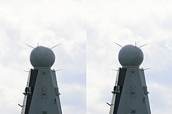
APAR (active phased-array radar): Thales Netherlands' multifunction radar is the primary sensor of the Royal Netherlands Navy's De Zeven Provinciën-class frigates, the German Navy's Sachsen-class frigates, and the Royal Danish Navy's Ivar Huitfeldt-class frigates. APAR is the first active electronically scanned array multifunction radar employed on an operational warship.[33]
1 2 Tomohiko Tada (March 2010). "4. Radar/ECM/ESM (Shipboard weapons of JMSDF 1952-2010)". Ships of the World (in Japanese) (721). Kaijin-sha: 100–105.
↑ "Air Defence Fire Control Radar". Defence Research and Development Organisation, Ministry of Defence, Government of India. Archived from the original on 2020-08-15. Retrieved 2021-10-07.
This page is based on this Wikipedia article Text is available under the CC BY-SA 4.0 license; additional terms may apply. Images, videos and audio are available under their respective licenses.