DisplayID

Last updated

DisplayID is a VESA standard for metadata describing display device capabilities to the video source. It is designed to replace E-EDID standard and EDID structure v1.4.

Contents

The DisplayID standard was initially released in December 2007. Version 1.1 was released in March 2009 and was followed by version 1.2 released in August 2011. Version 1.3 was released in June 2013 [1] and current version 2.0 was released in September 2017.

DisplayID uses variable-length structures of up to 256 bytes each, which encompass all existing EDID extensions as well as new extensions for 3D displays, embedded displays, Wide Color Gamut and HDR EOTF. DisplayID format includes several blocks which describe logical parts of the display such as video interfaces, display device technology, timing details and manufacturer information. Data blocks are identified with a unique tag. The length of each block can be variable or fixed to a specific number of bytes. Only the base data block is mandatory, while all extension blocks are optional. This variable structure is based on CEA EDID Extension Block Version 3 first defined in CEA-861-B.

The DisplayID standard is freely available and is royalty-free to implement.

DisplayID 2.0 structures

Version 2.0 introduces new generalized information blocks primarily intended for UltraHD High Dynamic Range (HDR) displays, such as LCD computer monitors and LCD/OLED televisions with native support for BT.2100 color space and PQ/HLG transfer functions. It also makes optional predefined CRT/LCD timings from DMT and CEA-861 standards, switching to formula-based structures which follow VESA CVT-RB and GTF.

The base DisplayID 2.0 variable-length structure is the same for all data blocks:

Variable-length DisplayID section structure, version 2.0 [2]
Byte offsetValueMandatoryDescription
00x20Green check.svgDisplayID Version 2, Revision 0
10–251Green check.svgLength of the variable data block
20–15Green check.svgDisplay primary use case (reserved in the extension sections):

0 = Extension section – same use case as the Base section
1 = Test structure (generated by testing equipment)
2 = Generic
3 = Television
4 = Productivity
5 = Gaming
6 = Presentation
7 = Virtual reality
8 = Augmented reality

3Green check.svgExtension count (reserved in the extension sections)
4Data blocks (N bytes)
(N+4)Green check.svgChecksum

Each data block starts with mandatory block tag, revision number (0-7), and payload length (0-248) bytes, and has a variable length of up to 251 bytes. The following blocks are currently defined:

Data block types [2]
Block tagMandatoryNameNotes
0x00–0x1FReserved (legacy 1.0 data blocks)
0x20Green check.svgProduct Identification
0x21Green check.svgDisplay ParametersPer primary use case
0x22Green check.svgType VII – Detailed timingPer primary use case
0x23Type VIII – Enumerated Timing Code
0x24Type IX – Formula-based Timing
0x25Dynamic video timing range Limits
0x26Green check.svgDisplay Interface FeaturesPer primary use case
0x27Stereo Display Interface
0x28Tiled Display Topology
0x29ContainerIDFor multi-function devices
0x7EVendor specific
0x81CTA DisplayID

0x20 Product identification

0x20 Product identification block contains standard vendor and product IDs, serial number, date of manufacture and product name.

Comparing to legacy block 0x00, Microsoft ISA Plug&Play identifier is replaced with IEEE OUI, first used in the network MAC address.

Product Identification block [2]
Byte offsetBit/valueDescription/format
00x20Product Identification block tag
10Revision
212–248Number of payload bytes
3–5Manufacturer/Vendor ID
IEEE Organizationally Unique Identifier (OUI)
6–7Product ID, LSB/MSB
8–11Serial number, optional
120–51, 255Week of Manufacture (0=unspecified); Model year tag (255)
130, 15–255Year of Manufacture/Model Year (0=unspecified); Stored Value = (Year-2000)
141–236Length of product name string
15–251Product name string, optional

0x21 Display parameters

0x21 Display parameters block contains basic parameters such as viewable area size and pixel count, supported color depth, and factory calibrated RGB color space, white point, luminance, and gamma transfer function.

Comparing to legacy block 0x01, color calibration values have been moved here from block 0x02 and max/min luminance values have been added. Display size can be specified in 1 mm increments in addition to default 0.1 mm.

Display Parameters block [2]
Byte offsetBit/valueDescription/format
00x21Display parameters block tag
1Bits 2:0 = 0Revision
Bit 7Image size precision:

0 = 0.1 mm (default)
1 = 1 mm

229Number of payload bytes
3–4Horizontal image size
5–6Vertical image size
7–8Horizontal pixel count
9–10Vertical pixel count
11Feature-support flags
Bits 2:0Scan orientation:

0 = Left–right, top–bottom (default)
1 = Right–left, top–bottom
2 = Top–bottom, right–left
3 = Bottom–top, right–left
4 = Right–left, bottom–top
5 = Left–right, bottom–top
6 = Bottom–top, left–right
7 = Top–bottom, left–right

Bits 4:3Max luminance information:

0 = non-zero values are a guaranteed minimum
1 = non-zero values are a guidance for the source device

Bit 6Color-space information:

0 = uses CIE 1931 (x,y) coordinates (default)
1 = uses CIE 1976 (u',v') coordinates

Bit 7Audio speakers information:

0 = integrated (default)
1 = external jack

12–14Primary Color 1 Chromaticity
Bits 7:0x/u' value, 8-bit LSB
Bits 11:8x/u' value, 4-bit MSB
Bits 15:12y/v' value, 4-bit LSB
Bits 23:16y/v' value, 8-bit MSB
15–17Primary color 2 chromaticity
18–20Primary color 3 chromaticity
21–23White point chromaticity
24–25Max luminance (full coverage), cd/m2
26–27Max luminance (10% coverage), cd/m2
28–29Min luminance, cd/m2
30Color-depth, display-technology flags
Bits 2:0Color Depth:

0 = not defined
1 = 6 bpc
2 = 8 bpc
3 = 10 bpc
4 = 12 bpc
5 = 16 bpc

Bits 6:4Display technology:

0 = not specified
1 = AMLCD
2 = AMOLED

31Gamma EOTF (1.00–3.54), stored value = (Gamma × 100) – 100 = (Gamma – 1) × 100 (255=unspecified)
Notes: Chromaticity values use 12-bit fractional integer numbers (bit12 × 2−1 + ... + bit0 × 2−12)

Luminance values use 16-bit IEEE 754-2008 half-precision floating-point format (−0 = not used)

0x22 Type VII detailed timings

0x22 Detailed timing block type VII defines CTA-861 compatible timings based on pixel rate. This block is based on type VI block 0x13.

Type VII – Detailed timing block header [2]
Byte offsetBit/valueDescription/format
00x22Detailed timing block tag
1Bits 2:0Revision: 0, 1
Bit 2DSC support

0 = Standard descriptor
1 = Descriptors with DSC pass-through (block revision 1)

220–240Number of payload bytes (N × 20, 1 ≤ N ≤ 12)
Type VII Detailed timing descriptor [2]
Byte offsetBit/valueDescription/format
0–2Pixel Clock, kHz (0.001–16,777.216 MPix/s)
Bits 7:08-bit LSB
Bits 15:88-bit middle bits
Bits 23:168-bit MSB
3Timing options
Bits 3:0Aspect ratio:

0 = 1:1
1 = 5:4
2 = 4:3
3 = 15:9
4 = 16:9
5 = 16:10
6 = 64:27
7 = 256:135
8 = Calculate using horizontal/vertical active image pixels/lines (bytes 4-5 and 12–13)

Bit 4Frame scanning type:

0 = progressive
1 = interlaced

Bits 6:5Stereoscopic 3D:

0 = mono timing
1 = 3D stereo timing
2 = mono or 3D stereo depending on user action

Bit 7Preferred timing:

1 = preferred detailed timing

4–5Horizontal active image pixels
6–7Horizontal blank pixels
8–9Horizontal offset (front porch)
Bits 7:08-bit LSB
Bits 14:87-bit MSB
Bit 15Horizontal sync polarity:

0 = negative
1 = positive

10–11Horizontal sync width
12–13Vertical active image lines
14–15Vertical blank lines
16–17Vertical sync offset (front porch)
Bits 7:08-bit LSB
Bits 14:87-bit MSB
Bit 15Vertical sync polarity:

0 = negative
1 = positive

18–19Vertical Sync Width

0x23 Type VIII enumerated timing code

0x23 Type VIII enumerated timing code block is based on type IV DMT ID block 0x06. It provides one-byte or two-byte video mode codes as defined in VESA Display Monitor Timings standard or Video Information Codes defined by CTA-861 and HDMI.

Type VIII – Enumerated timing code header [2]
Byte offsetBit/valueDescription/format
00x23Enumerated timing code block tag
1Bits 2:0 = 0Revision
Bit 3Timing code size:

0 = one-byte descriptor
1 = two-byte descriptor

Bits 7:6Timing code type:

0 = DMT
1 = CTA VIC code
2 = HDMI VIC code

21–248Number of payload bytes

0x24 Type IX formula-based timings

0x24 Type IX formula-based timings block is based on type V short timings block 0x11.

Type IX – Formula-based timing header [2]
Byte offsetBit/valueDescription/format
00x24Formula-based timing block tag
1Bits 2:0 = 0Revision
26–248Number of payload bytes (N × 6)
Type IX Formula-based timing descriptor [2]
Byte offsetBit/valueDescription/format
0Timing options
Bits 2:0Timing Formula/Algorithm

0 = CVT
1 = CVT-RB
2 = CVT-R2

Bit 3NTSC Video optimized refresh rate × (1000/1001):

0 = not supported
1 = supported

Bits 6:5Stereoscopic 3D:

0 = Mono timing
1 = 3D stereo timing
2 = Mono or 3D stereo depending on user action

1–2Horizontal active image pixels
3–4Vertical active image lines
5vertical refresh rate, Hz (1-256)

0x25 Dynamic video timing range

0x25 Dynamic video timing range block is based on block 0x9h Video Timing Range Limits; the new version allows more precise definition of pixel rate in 1 kHz steps and adds indication for variable refresh rates.

Dynamic video timing range block [2]
Byte offsetBit/valueDescription/format
00x25Dynamic video timing range block tag
1Bits 2:0Revision: 0, 1
29Number of payload bytes
3–5Minimum pixel clock, kHz
6–8Maximum pixel clock, kHz
9Minimum vertical refresh rate, Hz
10Maximum vertical refresh rate LSB, Hz
11Dynamic video timing range Support Flags
Bits 1:0Maximum vertical refresh rate MSB, Hz (block revision 1)
Bit 7Seamless dynamic video timing change:

0 = not supported
1 = supported with fixed horizontal pixel rate and dynamic vertical blanking

0x26 Display interface features

0x26 Display interface features block describes color depth, dynamic range, and transfer function supported by the display controller. It is based on blocks 0x0F display interface features and 0x02 color characteristics.

Display Interface Features block [2]
Byte offsetBit/valueDescription/format
00x26Display interface features block tag
1Bits 2:0 = 0Revision
29Number of payload bytes
3Color-depth support, RGB encoding
Bit 06 bpc
Bit 18 bpc
Bit 210 bpc
Bit 312 bpc
Bit 414 bpc
Bit 516 bpc
0 = no support

1 = supported

4Color-depth support, YCbCr 4:4:4 encoding
5Color-depth support, YCbCr 4:2:2 encoding
Bit 08 bpc
Bit 110 bpc
Bit 212 bpc
Bit 314 bpc
Bit 416 bpc
0 = no support

1 = supported

6Color-depth support, YCbCr 4:2:0 encoding
7Minimum pixel rate for YCbCr 4:2:0 encoding,
pixel rate = 74.25 MP/s × Stored Value (0=supported at all modes)
8Audio capability and feature support flags
Bit 548 kHz sample rate
Bit 644.1 kHz sample rate
Bit 732 kHz sample rate
0 = no support

1 = supported

9Color space and EOTF combination 1
Bit 0sRGB (IEC 61966-2-1) Color space and EOTF
Bit 1ITU-R BT.601 Color space and EOTF
Bit 2ITU-R BT.709 Color space and ITU-R BT.1886 EOTF
Bit 3Adobe RGB Color space and EOTF
Bit 4DCI-P3 (SMPTE RP 431–2) Color space and EOTF
Bit 5ITU-R BT.2020 Color space and EOTF
Bit 6ITU-R BT.2020 Color space and SMPTE ST 2084 EOTF
0 = no support

1 = supported

100Color space and EOTF combination 2: reserved
110–7Number of additional color space and EOTF bytes (N)
11+#NAdditional color space and EOTF byte #N
Bits 3:0EOTF:

0 = defined by display interface rules
1 = sRGB (IEC 61966-2-1)
2 = ITU-R BT.601
3 = ITU-R BT.1886 for ITU-R BT.709
4 = Adobe RGB
5 = DCI-P3 (SMPTE RP 431–2)
6 = ITU-R BT.2020
7 = Gamma function (value stored in Display Parameters byte 31)
8 = SMPTE ST 2084
9 = Hybrid log–gamma
10 = Custom (details defined in another block)

Bits 3:0Color space:

0 = Undefined – follow display interface rules
1 = sRGB (IEC 61966-2-1)
2 = ITU-R BT.601
3 = ITU-R BT.709
4 = Adobe RGB
5 = DCI-P3 (SMPTE RP 431–2)
6 = ITU-R BT.2020
7 = Custom (details defined in another block)

0x27 Stereo display interface

0x27 Stereo display interface block is based on block 0x10and describes stereoscopic 3D/VR modes (i.e. timings codes and stereo frame formats) supported by the display.

Stereo Display Interface block [2]
Byte offsetBit/valueDescription/format
00x27Stereo Display Interface block tag
1Bits 2:0Revision: 0, 1
Bits 7:6Stereoscopic 3D Timing:

0 = 0b00 = block applies to all 3D timings
1 = 0b01 = block applies to 3D timings with specified Timing Code (block revision 1)
2 = 0b10 = block applies to all timings in any timing block
3 = 0b11 = block applies to timings with specified Timing Code (block revision 1)

2(N+2)Number of payload bytes
3(N+1)Number of bytes in Stereo Interface Method block
4Stereo Interface Method code:

0 = Frame/Field Sequential (N=1)
1 = Side-by-Side (N=1)
2 = Pixel Interleaved (N=8)
3 = Dual Interface (N=1)
4 = Multi-view (N=2)
5 = Stacked Frame (N=1)
255 = Vendor defined (N=0)

5Stereo Interface Method-specific Parameters (N bytes)
5+N3D Timings descriptor 1
Bits 4:0Timing Code number (M1, 1-31)
Bits 7:6Timing Code Type:

0 = DMT
1 = CTA VIC code
2 = HDMI VIC code

(6+N+#M1)One-byte Timing Code #M1
(7+N+M1)3D Timings descriptor 2
(6+N+M1+#M2)One-byte Timing Code #M2
Note: 3D Timings descriptors only exist when byte 1 bit 6 = 1
Stereo Display Interface Method-specific Parameters [2]
N, BytesBit/valueDescription/format
1Method code: 0 = Frame/Field Sequential
Bit 0Stereo Polarity:

0 = Stereo Sync on left eye image
1 = Stereo Sync on right eye image

11 = Side-by-Side
Bit 0View Identify:

0 = Left half represents left eye image
1 = Left half represents right eye image

82 = Pixel Interleaved
Bits 7:0Interleave pattern – 8x8 bit mask

0 = Pixel position for right eye image
1 = Pixel position for left eye image

13 = Dual Interface
Bit 0Interface Left and Right Polarity:

0 = Interface carries right eye image
1 = Interface carries left eye image

Bits 2:1Mirroring

0 = No mirroring
1 = Left/Right are mirrored
1 = Top/Bottom are mirrored

24 = Multi-view
Number of Views
View Interleaving Method Code
15 = Stacked Frame
Bit 0View Identity:

0 = Top is left-eye image, bottom is right-eye image

0x28 Tiled display topology

0x28 Tiled display topology block describes displays that consist of multiple physical display panels, each driven by a separate video interface. It is based on block 0x12.

Tiled Display Topology block [2]
Byte offsetBit/valueDescription/format
00x28Tiled Display Topology block tag
1Bits 2:0 = 0Revision
222Number of payload bytes
3Tiled Display and Tile Capabilities
Bits 2:0Tile Behavior when the only tile being transmitted:

0 = None of the following
1 = Display at Tile Location (byte 5)
2 = Scale to fit the display
3 = Clone to other tiles

Bits 4:3Tile Behavior when N tiles (1 < N < Max, N<>2) are being transmitted:

0 = None of the following
1 = Display at Tile Location (byte 5)

Bit 6Tile Bezel Descriptor:

0 = Not available
1 = Available at bytes 11-15

Bit 7Physical Display Enclosure:

0 = Multiple physical enclosures
1 = Single physical enclosure

4–6Tiled Display Topology and Tile Location
4Total Number of Tiles
Bits 3:0Number of Vertical Tiles, 4-bit LSB
Bits 7:4Number of Horizontal Tiles, 4-bit LSB
5Tile Location
Bits 3:0Vertical Tile Location, 4-bit LSB
Bits 7:4Horizontal Tile Location, 4-bit LSB
6Tile Location and Total Number of Tiles
Bits 1:0Vertical Tile Location, 2-bit MSB
Bits 3:2Horizontal Tile Location, 2-bit MSB
Bits 5:4Number of Vertical Tiles, 2-bit MSB
Bits 7:6Number of Horizontal Tiles, 2-bit MSB
7–10Tile Size
Bits 7:0Horizontal Size, 8-bit LSB
Bits 15:8Horizontal Size, 8-bit MSB
Bits 23:16Vertical Size, 8-bit LSB
Bits 31:24Vertical Size, 8-bit MSB
11–15Tile Pixel Multiplier and Tile Bezel-related Information
11Tile Pixel Multiplier
12Tile Top Bezel Size
13Tile Bottom Bezel Size
14Tile Right Bezel Size
15Tile Left Bezel Size
Note: Tile Bezel in pixels = (Tile Pixel Multiplier × Tile Bezel Size × 0.1)
16–24Tiled Display Topology ID
16–18Tiled Display Manufacturer/Vendor ID
IEEE Organizationally Unique Identifier (OUI)
19–20Tiled Display Product ID LSB/MSB
21–24Serial number, optional

0x29 Container ID

0x29 Container ID block defines a unique identifier used to associate additional devices that may be present in a multifunctional display.

ContainerID block [2]
Byte offsetBit/valueDescription/format
00x29ContainerID block tag
1Bits 2:0 = 0Revision
216Number of payload bytes
3–18Bits 128:0ContainerID
Universally Unique Identifier (UUID)

0x7E Vendor-specific data

0x7E Vendor-specific data includes proprietary parameters which are not supported by DisplayID 2.0 structures.

Vendor-specific data block [2]
Byte offsetBit/valueDescription/format
00x7EVendor-specific block tag
1Bits 2:0Revision
23–248Number of payload bytes
3–5Manufacturer/Vendor ID
IEEE Organizationally Unique Identifier (OUI)
6–224Payload bytes
VESA Vendor-specific data block [2]
Byte offsetBit/valueDescription/format
00x7EVendor-specific block tag
1Bits 2:0 = 1Revision
2–40x3A0292VESA OUI
5Bits 2:0Structure type:

0 = Embedded DisplayPort (eDP)
1 = External DisplayPort

Bit 7Default Color space and EOTF handling:

0 = interpret "RGB unspecified color space" as sRGB Color space and EOTF
1 = interpret as "native" color space, EOTF is specified in the Display Parameters block 0x21

6Bits 3:0Number of horizontal pixels overlapping an adjacent panel segment: 0-8
Bits 6:5Multi-SST operation:

0 = 0b00 = not supported (Conventional Single-Stream Transport)
1 = 0b01 = two streams (two or four links)
2 = 0b10 = four streams (four links)

7Bits 5:0Pass-through timing, integer target DSC bpp (bits per pixel)
8Bits 3:0Pass-through timing, fractional target DSC bpp (bits per pixel)

0x81 CTA DisplayID

0x81 CTA DisplayID block provides information on CTA-861 EDID timings.

CTA DisplayID block header [2]
Byte offsetBit/valueDescription/format
00x81CTA DisplayID block tag
1Bits 2:0 = 0Revision
23–248Number of payload bytes
3CTA Block 1 Tag Code and Block 1 Length
Bits 4:0Block 1 Length (L1)
Bits 7:5Tag code (CTA-861-G)
4-L1CTA Block 1 Descriptor #L1
(L1+2)CTA Block 2 Tag Code and Block 2 Length

DisplayID 1.3 structures

Version 1.3 information blocks 0x10-0x1F borrow heavily from EDID 1.4 standard, which was designed for previous generation CRT/LCD/DLP/PDP displays.

Variable-length DisplayID section structure, version 1.3 [3]
Byte offsetValueMandatoryDescription
00x12Green check.svgDisplayID Version 1, Revision 3
20–15Green check.svgDisplay Type Identifier:

0 = Extension section – same use case as the Base section
1 = Test structure (generated by testing equipment)
2 = Display panel
3 = Monitor
4 = Television
5 = Repeater
6 = Direct-drive monitor

The following block types are defined:

Data block types [3]
Block tagName
0x00Product identification
0x01Display parameters
0x02Color characteristics
0x03Type I timing – detailed
0x04Type II timing – detailed
0x05Type III timing – short
0x06Type IV timing – DMT ID code
0x07VESA timing standard
0x08CEA Timing Standard
0x09Video timing range
0x0AProduct serial number
0x0BGeneral-purpose ASCII string
0x0CDisplay device data
0x0DInterface power sequencing
0x0ETransfer characteristics
0x0FDisplay interface data
0x10Stereo display interface
0x11Type V timing – short
0x13Type VI timing – detailed
0x7FVendor specific

Note: where indicated, only the difference from similar/superseding structures in Version 2.0 are shown in the sections below.

0x00 Product identification

0x00 Product identification – superseded by 0x20. The difference is:

Product Identification block [3]
Byte offsetBit/valueDescription/format
00x00Product identification block tag
3–5Manufacturer/vendor ID
Microsoft ISA Plug&Play ID (PnPID)

0x01 Display parameters

0x01 Display parameters – superseded by 0x21. The differences are:

Display Parameters block [3]
Byte offsetBit/valueDescription/format
00x01Display parameters block tag
11Feature-support flags
Bit 0Deinterlacing
Bit 1Support_AI in ACP/ISRC packets
Bit 2Single fixed pixel format only
Bit 3Single fixed timing only
Bit 4VESA display power management
Bit 5Audio input override
Bit 6Separate audio inputs
Bit 7Audio support
0 = no support/no

1 = supported/yes

12Transfer characteristic gamma EOTF (1.00–3.54), stored value = (Gamma × 100) – 100 = (Gamma – 1) × 100 (255=unspecified)
13Aspect ratio = long axis / short axis (1.00–3.55), stored value = (AR – 1) × 100 (78 for 16:9)
14Color bit depth
Bits 3:0Panel native dynamic range, stored value = bpc – 1
Bits 7:4Display device overall dynamic range, stored value = bpc – 1

0x02 Color characteristics

0x02 Color characteristics – superseded by 0x21 Display parameters.

Color characteristics block [3]
Byte offsetBit/valueDescription/format
00x02Color characteristics block tag
1Bits 2:0 = 1Revision
Bits 6:3Transfer characteristic block number
(block 0x0E)
Bit 7Color space information:

0 = uses CIE 1931 (x,y) coordinates (default)
1 = uses CIE 1976 (u',v') coordinates

2(Np + Nw) × 3 [ + 1 ]Number of payload bytes; add 1 if Np=0
3Color characteristics information
Bits 3:0Number of white points (Nw)
Bits 6:4Number of primaries (Np)
(0=Standard color space, additional Identifier byte is added to the block payload)
Bit 7Color mode:

0 = Spatial – separate subpixels for each primary color
1 = Temporal – field-sequential color (DLP)

4–6Color primary or white point chromaticity
Bits 7:0x/u' value, 8-bit LSB,
or
Standard color space identifier code if Np=0:

0 = sRGB (IEC 61966-2-1)
1 = ITU-R BT.601
2 = ITU-R BT.709
3 = Adobe RGB
4 = DCI-P3 (SMPTE RP 431–2)
5 = NTSC "SMPTE C" (SMPTE RP 145)
6 = PAL (ITU-R BT.470)
7 = Adobe Wide Gamut RGB
8 = DICOM (PS3.14 Grayscale standard display function)

Bits 11:8x/u' value, 4-bit MSB
Bits 15:12y/v' value, 4-bit LSB
Bits 23:16y/v' value, 8-bit MSB
Notes: Chromaticity values use 12-bit fractional integer numbers (bit12 × 2−1 + ... + bit0 × 2−12)

0x03 Type I detailed timings

0x03 Type I detailed timings – superseded by 0x22 type VII detailed timings. The differences are:

Type I – Detailed timing block header [2]
Byte offsetBit/valueDescription/format
00x03Detailed timing block tag
1Bits 2:0 = 1Revision
Type I Detailed timing descriptor [2]
Byte offsetBit/valueDescription/format
0–2Pixel clock, 10 kHz steps (0.01–167,772.16 MPix/s)
3Timing options
Bits 3:0Aspect ratio:

8 = Not defined

0x04 Type II detailed timings

0x04 Type II detailed timings block provides a compressed structure with less precise pixel coordinates and reduced blank intervals comparing to Type I:

Type II – Detailed timing block header [2]
Byte offsetBit/valueDescription/format
00x04Detailed timing block tag
1Bits 2:0 = 0Revision
211–242Number of payload bytes (N × 11, 1 ≤ N ≤ 22)
Type II Detailed timing descriptor [2]
Byte offsetBit/valueDescription/format
0–2Pixel clock, 10 kHz steps (0.01–167,772.16 MPix/s)
3Timing options
Bit 2Vertical sync polarity:

0 = negative
1 = positive

Bit 3Horizontal sync polarity:

0 = negative
1 = positive

4Horizontal active image pixels, 8-bit LSB
5Bits 7:1Horizontal blank pixels
Bit 0Horizontal active image pixels, 1-bit MSB
6Horizontal sync offset (front porch) and width
Bits 3:0Sync offset (front porch)
Bits 7:4Sync width
7Vertical active image lines, 8-bit LSB
8Bits 4:0Vertical active image pixels, 4-bit MSB
9Vertical blank lines
10Vertical sync offset (front porch) and width
Bits 3:0Sync offset (front porch)
Bits 7:4Sync width
Note: For all pixel dimensions, stored value = (Pixels / 8) – 1

0x05 Type III short timings

0x05 Type III short timings block provides a very short compressed structure which uses formula-based CVT timings.

Type III – Short timing block header [2]
Byte offsetBit/valueDescription/format
00x05Short timing block tag
1Bits 2:0 = 1Revision
26–248Number of payload bytes (N × 3, 1 ≤ N ≤ 82)
Type III short timing descriptor [2]
Byte offsetBit/valueDescription/format
0Timing options
Bits 6:4Timing formula/algorithm

0 = CVT
1 = CVT-RB

Bits 3:0Aspect ratio
1Horizontal active image pixels
2Frame transfer type and rate
Bit 7Frame transfer type:

0 = progressive
1 = field interlaced

Note: For all pixel dimensions, stored value = (Pixels / 8) – 1

0x06 Type IV short timings

0x06 Type IV short timing (DMT ID code) block uses video mode codes defined in VESA display monitor timings standard, as well as video information codes defined by CTA-861 and HDMI. Superseded by 0x23 enumerated timing.

Type IV – Short timing DMT ID code header [2]
Byte offsetBit/valueDescription/format
00x06Type IV – Short timing (DMT ID code) block tag
1Bits 2:0 = 1Revision
Bits 7:6Timing code type:

0 = DMT
1 = CTA VIC code
2 = HDMI VIC code

21–248Number of payload bytes

0x11 Type V short timings

0x11 Type V short timings block is based on Type III short timings block 0x05, but provides greater pixel precision and only supports CVT-RB. Superseded by 0x24 Type IX formula-based timings.

Type V – Short timing header [2]
Byte offsetBit/valueDescription/format
00x11Type V – Short timing block tag
1Bits 2:0 = 0Revision
26–248Number of payload bytes (N × 7, 1 ≤ N ≤ 35)
Type V short timing descriptor [2]
Byte offsetBit/valueDescription/format
0Timing options
Bits 1:0Timing formula/algorithm

0 = CVT-RB2
1 = CVT-RB

Bit 4NTSC Video optimized refresh rate × (1000/1001):

0 = not supported
1 = supported

Bits 6:5Stereoscopic 3D:

0 = Mono timing
1 = 3D stereo timing
2 = Mono or 3D stereo depending on user action

Bit 7Preferred timing:

1 = preferred detailed timing

1–2Horizontal active image pixels
3–4Vertical active image lines
5Vertical Refresh Rate, Hz (1–256)

0x13 Type VI detailed timing

0x13 Type VI Detailed timing block supports higher precision pixel clock and high-resolution timings. This block is based on Type I block 0x03, but allows greater timings precision using 1 kHz steps instead of 10 kHz. Superseded by 0x22 Type VII Detailed timings.

Type VI – Detailed timing block header [2]
Byte offsetBit/valueDescription/format
00x13Type VI detailed timing block tag
1Bits 2:0 = 0Revision
2Number of payload bytes (N × 17 + M × 14)
Type VI Detailed timing descriptor [2]
Byte offsetBit/valueDescription/format
0–2Pixel clock, kHz (0.001–4,194.303 MPix/s)
Bits 7:08-bit LSB
Bits 15:88-bit middle bits
Bits 21:166-bit MSB
Bit 22Aspect and size information:

0 = not included
1 = included in bytes 14–16

Bit 23Preferred timing:

0 = not a preferred detailed timing
1 = preferred detailed timing

3–4Horizontal active image pixels & timing
Bits 7:0Horizontal active image pixels, 8-bit LSB
Bits 14:8Horizontal active image pixels, 7-bit MSB
Bit 16Horizontal Sync Polarity:

0 = negative
1 = positive

5–6Vertical active image lines & timing
Bits 7:0Vertical active image lines, 8-bit LSB
Bits 14:8Vertical active image lines, 7-bit MSB
Bit 16Vertical Sync Polarity:

0 = negative
1 = positive

7–9Horizontal blank pixels & front porch
Bits 7:0Horizontal blank pixels, 8-bit LSB
Bits 15:8Horizontal offset (front porch), 8-bit LSB
Bits 19:16Horizontal blank pixels, 4-bit MSB
Bits 23:20Horizontal offset (front porch), 4-bit MSB
10Horizontal Sync Width
11Vertical Blank Lines
12Vertical Sync offset (front porch)
13Vertical Sync Width and Timing
Bits 3:0Vertical Sync Width
Bits 6:5Stereoscopic 3D:

0 = mono timing
1 = 3D stereo timing
2 = mono or 3D stereo depending on user action

Bit 7Frame scanning type:

0 = progressive
1 = interlaced

14Aspect multiplier, aspect ratio = Aspect Multiplier × 3 / 256
15–16Vertical image base size and size multiplier
Bits 7:0Vertical image base size, 8-bit LSB
Bits 11:8Vertical image base size, 4-bit MSB
Bits 15:12Size Multiplier
Vertical image size = Vertical image base size × Size Multiplier

0x09 Video timing range limits

0x09 Video timing range limits block describes displays capable of variable timings. Superseded by 0x25 Dynamic video timings range.

Video timing range limits block [2]
Byte offsetBit/valueDescription/format
00x09Video timing range limits block tag
1Bits 2:0 = 0Revision
29Number of payload bytes
3–5Minimum pixel clock, 10 kHz steps
6–8Maximum pixel clock, 10 kHz steps
9Minimum Horizontal Frequency, kHz
10Maximum Horizontal Frequency, kHz
11–12Minimum Horizontal Blanking Pixels
13Minimum Vertical Refresh Rate, Hz
14Maximum Vertical Refresh Rate, Hz
15–16Minimum Vertical Blanking Lines
17Video timing support flags
Bit 4Discrete frequency display
Bit 5VESA CVT
Bit 6VESA CVT-RB
Bit 7Interlaced
0 = no support/no

1 = supported/yes

0x0C Display device data

0x0C Display device data block provides information about display panel characteristics for embedded applications, such as display technology, panel type, and pixel response times.

Display device data block [2]
Byte offsetBit/valueDescription/format
00x0CDisplay device data block tag
1Bits 2:0 = 0Revision
213Number of payload bytes
3Display device technology and sub-type codes
Bits 7:0CRT

0=0x00 = Monochrome CRT
1=0x01 = Tricolor CRT
2=0x02 = Other CRT
LCD
16=0x10 = Passive matrix TN (HTN, STN)
17=0x11 = Passive matrix cholesteric LC
18=0x12 = Passive matrix ferroelectric LC
19=0x13 = Other passive matrix LC
20=0x14 = Active matrix TN
21=0x15 = Active matrix IPS
22=0x16 = Active matrix VA
22=0x16 = Active matrix OCB
22=0x16 = Active matrix ferroelectric
31=0x1F = Other LC
Plasma display (PDP)
32=0x20 = DC plasma
33=0x21 = AC plasma
Other display technology
48=0x30 = Electroluminescent (except OLED/OEL)
64=0x40 = Inorganic LED
80=0x50 = OLED/OEL
96=0x60 = FED/SED (cold-cathode, phosphor-based)
112=0x70 = Electrophoretic
128=0x80 = Electrochromic
144=0x90 = Electromechanic
160=0xA0 = Electrowetting
240=0xF0 = Other

Bits 7:4Display Technology, 4-bit MSB

0 = CRT
1 = LCD
2 = PDP
3 = ELD
4 = LED
5 = OLED/OEL
6 = FED/SED
7 = Ep
8 = Ec
9 = Em
10=0xA = Ew
15=0xF = Other

4Display Device Operating Mode & Flags
Bit 2Backlight can be switched off
Bit 3Backlight intensity can be controlled
0 = no support/no

1 = supported/yes

Bits 7:4Operating Mode code:

0 = Direct-view reflective, ambient lighting (no illumination)
1 = Direct-view reflective, illuminated, ambient lighting (no illumination) by default
2 = Direct-view reflective, illuminated
3 = Direct-view transmissive, ambient lighting (no illumination)
4 = Direct-view transmissive, illuminated, ambient lighting (no illumination) by default
5 = Direct-view transmissive, illuminated
6 = Direct-view emissive
7 = Direct-view transflective, reflective (backlight off) by default
8 = Direct-view transflective, transmissive (backlight on) by default
9 = Transparent, viewable in ambient light
10 = Transparent emissive
11 = Projection, reflective light modulator (DLP/LCOS)
12 = Projection, transmissive light modulator (LCD projection)
13 = Projection, emissive image transducer (CRT projection)

5–8Display Device Native Pixel Format
5–6Horizontal pixel count
7–8Vertical pixel count
9–10Aspect Ratio and Orientation
9Aspect Ratio = long axis / short axis (1.00–3.55), stored value = (AR – 1) × 100 (78 for 16:9)
10Orientation
Bits 1:0Scan direction:

0 = Not defined/no raster scan
1 = Line (fast scan) on long axis, frame/field (slow scan) on short axis
2 = Line (fast scan) on short axis, frame/field (slow scan) on long axis

Bits 3:2Zero pixel location:

0 = Upper left corner
1 = Upper right corner
2 = Lower left corner
3 = Lower right corner

Bits 5:4Rotation capability:

0 = No rotation
1 = Clockwise 90°
2 = Counter-clockwise 90°
2 = 90° in either direction

Bits 7:6Orientation:

0 = Landscape (horizontal long axis)
1 = Portrait (vertical long axis)
2 = Not fixed (can be rotated by user)

11RGB Sub-pixel Information codes:

0 = Not defined
1 = RGB vertical stripes
2 = RGB horizontal stripes
3 = Vertical stripes, ordered as in Display Chromaticity block
4 = Horizontal stripes, ordered as in Display Chromaticity block
5 = RGGB 2x2 quad structure, red at top left, blue at bottom right
6 = RGGB 2x2 quad structure, red at bottom left, blue at top right
7 = Triad (delta)
8 = Mosaic (delta)
9 = RGBE/RGBW 2x2 quad structure, any order
10 = Five subpixels – RGB vertical and two colors above and below
11 = Six subpixels – RGB vertical and three colors in any order
11 = PenTile

12Horizontal Pixel Pitch, in 0.01 mm steps (0.01% for projection)
13Vertical Pixel pitch, in 0.01 mm steps (0.01% for projection)
14Color Bit Depth
Bits 3:0Panel native dynamic range, stored value = bpc – 1
15Response Time
Bits 6:0Pixel response time, in ms (clamped to 0 and 126)
Bit 7Measurement method:

0 = Black to white (lower to higher) transition
1 = White to black (higher to lower) transition

0x0F Display interface data

Display interface features block – superseded by 0x26 Display Interface Features.

Display Interface Data block [2]
Byte offsetBit/valueDescription/format
00x0FDisplay Interface Features block tag
1Bits 2:0 = 0Revision
210Number of payload bytes
3Interface Type and Number of Links
Bits 3:0Number of links (1, 2, or 4),

or
Analog sub-type (if bits 7:4 = 0):
0 = 15HD/VGA (VESA EDDC Standard)
1 = VESA NAVI-V (15HD)
2 = VESA NAVI-D

Bits 7:4Display Interface Type:

0 = Analog
1 = LVDS (generic)
2 = TMDS (generic)
3 = RSDS (generic)
4 = DVI-D
5 = DVI-I, analog
6 = DVI-I, digital
7 = HDMI-A
8 = HDMI-B (dual link)
9 = MDDI
10 = DisplayPort
11 = Proprietary digital interface

4Interface Standard Version and Revision
Bits 3:0Interface revision
Bits 7:4Interface version
5Color Depth Support, RGB encoding
Bit 06 bpc
Bit 18 bpc
Bit 210 bpc
Bit 312 bpc
Bit 414 bpc
Bit 516 bpc
0 = no support

1 = supported

6Color Depth Support, YCbCr 4:4:4 encoding
7Color Depth Support, YCbCr 4:2:2 encoding
Bit 08 bpc
Bit 110 bpc
Bit 212 bpc
Bit 314 bpc
Bit 416 bpc
0 = no support

1 = supported

8Content Protection support:

0 = No support
1 = HDCP
2 = DTCP
3 = DPCP

9Content Protection Standard Version and Revision
Bits 3:0Standard revision
Bits 7:4Standard version
10Spread Spectrum Information
Bits 3:0Spread percentage, in 0.1% increments (range 0 to 1.5%)
Bits 7:6Spread type supported:

0 = No support
1 = Down spread
2 = Center spread

11Interface type dependent attribute 1
Bit 03.3 V
Bit 15 V
Bit 212 V
Bit 32.8 V
0 = no support

1 = supported

Bit 4Color mapping:

0 = NS (Normal) mode
1 = 6-bit compatible mode

12Interface type dependent attribute 2
Bit 0Shift clock data strobe:

0 = Falling edge
1 = Rising edge

Bit 1DE polarity:

0 = Active high (high signal level)
1 = Active low (low signal level)

Bit 2DE mode :

0 = DE (data enable) mode
1 = Fixed mode (VSync/HSync)

Additional blocks

Data blocks not described above are:

0x0A Serial number data block provides product serial number as an ASCII string.

0x0B General-purpose ASCII string block provides general purpose text strings that may be required by specific applications.

0xD0 Interface power sequencing block defines display interface signal timings required for entering and exiting sleep mode.

0x0E Transfer characteristics block defines detailed gamma curves according to VESA display transfer characteristic data block (DTCDB) standard, as may be required by byte 1 in 0x02 color characteristics block.

0x10 Stereo display interface block describes stereoscopic 3D/VR modes – superseded by 0x27 Ssereo display interface.

0x12 Tiled display topology data block defines multi-panel displays – superseded by 0x28 tiled display topology.

0x7F Vendor specific block defines proprietary vendor data.

See also

Related Research Articles

<span class="mw-page-title-main">Digital Visual Interface</span> Standard for transmitting digital video to a display

Digital Visual Interface (DVI) is a video display interface developed by the Digital Display Working Group (DDWG). The digital interface is used to connect a video source, such as a video display controller, to a display device, such as a computer monitor. It was developed with the intention of creating an industry standard for the transfer of uncompressed digital video content.

<span class="mw-page-title-main">Video Electronics Standards Association</span> Technical standards organization for computer display standards

VESA, formally known as Video Electronics Standards Association, is an American technical standards organization for computer display standards. The organization was incorporated in California in July 1989 and has its office in San Jose. It claims a membership of over 300 companies.

VESA BIOS Extensions (VBE) is a VESA standard, currently at version 3, that defines the interface that can be used by software to access compliant video boards at high resolutions and bit depths. This is opposed to the "traditional" INT 10h BIOS calls, which are limited to resolutions of 640×480 pixels with 16 colour (4-bit) depth or less. VBE is made available through the video card's BIOS, which installs during boot up some interrupt vectors that point to itself.

<span class="mw-page-title-main">Video Graphics Array</span> Computer display standard and resolution

Video Graphics Array (VGA) is a video display controller and accompanying de facto graphics standard, first introduced with the IBM PS/2 line of computers in 1987, which became ubiquitous in the IBM PC compatible industry within three years. The term can now refer to the computer display standard, the 15-pin D-subminiature VGA connector, or the 640 × 480 resolution characteristic of the VGA hardware.

Extended Display Identification Data (EDID) and Enhanced EDID (E-EDID) are metadata formats for display devices to describe their capabilities to a video source. The data format is defined by a standard published by the Video Electronics Standards Association (VESA).

SOCKS is an Internet protocol that exchanges network packets between a client and server through a proxy server. SOCKS5 optionally provides authentication so only authorized users may access a server. Practically, a SOCKS server proxies TCP connections to an arbitrary IP address, and provides a means for UDP packets to be forwarded.

The BMP file format or bitmap, is a raster graphics image file format used to store bitmap digital images, independently of the display device, especially on Microsoft Windows and OS/2 operating systems.

The Display Data Channel, or DDC, is a collection of protocols for digital communication between a computer display and a graphics adapter that enable the display to communicate its supported display modes to the adapter and that enable the computer host to adjust monitor parameters, such as brightness and contrast.

<span class="mw-page-title-main">HDMI</span> Proprietary interface for transmitting digital audio and video data

High-Definition Multimedia Interface (HDMI) is a proprietary audio/video interface for transmitting uncompressed video data and compressed or uncompressed digital audio data from an HDMI-compliant source device, such as a display controller, to a compatible computer monitor, video projector, digital television, or digital audio device. HDMI is a digital replacement for analog video standards.
<span class="mw-page-title-main">VGA connector</span> 15-pin video connector

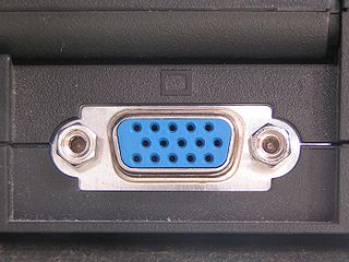
The Video Graphics Array (VGA) connector is a standard connector used for computer video output. Originating with the 1987 IBM PS/2 and its VGA graphics system, the 15-pin connector went on to become ubiquitous on PCs, as well as many monitors, projectors and high-definition television sets.

CTA-708 is the standard for closed captioning for ATSC digital television (DTV) streams in the United States and Canada. It was developed by the Consumer Electronics sector of the Electronic Industries Alliance, which later became the standalone organization Consumer Technology Association.
<span class="mw-page-title-main">VESA Digital Flat Panel</span>

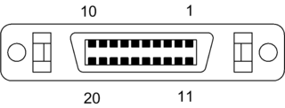
The VESA Digital Flat Panel (DFP) interface standard specifies a video connector and digital TMDS signaling for flat-panel displays. It features 20 pins and uses the PanelLink protocol; the standard is based on the preceding VESA Plug and Display (P&D) standard, ratified in 1997. Unlike the later, electrically-compatible Digital Visual Interface, DFP never achieved widespread implementation.

<span class="mw-page-title-main">DisplayPort</span> Digital display interface

DisplayPort (DP) is a digital display interface developed by a consortium of PC and chip manufacturers and standardized by the Video Electronics Standards Association (VESA). It is primarily used to connect a video source to a display device such as a computer monitor. It can also carry audio, USB, and other forms of data.

The following are common definitions related to the machine vision field.

Coordinated Video Timings is a standard by VESA which defines the timings of the component video signal. Initially intended for use by computer monitors and video cards, the standard made its way into consumer televisions.

ARINC 818: Avionics Digital Video Bus (ADVB) is a video interface and protocol standard developed for high bandwidth, low-latency, uncompressed digital video transmission in avionics systems. The standard, which was released in January 2007, has been advanced by ARINC and the aerospace community to meet the stringent needs of high performance digital video. The specification was updated and ARINC 818-2 was released in December 2013, adding a number of new features, including link rates up to 32X fibre channel rates, channel-bonding, switching, field sequential color, bi-directional control and data-only links.

Generalized Timing Formula is a standard by VESA which defines exact parameters of the component video signal for analogue VGA display interface.

<span class="mw-page-title-main">FreeSync</span> Brand name for an adaptive synchronization technology

FreeSync is an adaptive synchronization technology for LCD and OLED displays that support a variable refresh rate aimed at avoiding tearing and reducing stuttering caused by misalignment between the screen's refresh rate and the content's frame rate.

Display Stream Compression (DSC) is a VESA-developed video compression algorithm designed to enable increased display resolutions and frame rates over existing physical interfaces, and make devices smaller and lighter, with longer battery life. It is a low-latency algorithm based on delta PCM coding and YCGCO-R color space.

References

  1. "VESA Refreshes DisplayID Standard to Support Higher Resolutions and Tiled Displays". vesa.org. 2013-09-23. Retrieved 2013-12-24.
  2. 1 2 3 4 5 6 7 8 9 10 11 12 13 14 15 16 17 18 19 20 21 22 23 24 25 26 27 28 29 30 31 32 VESA DisplayID Standard, Version 2.0. September 11, 2017
  3. 1 2 3 4 5 VESA DisplayID Standard, Version 1.3. July 5, 2013