An amplifier, electronic amplifier or (informally) amp is an electronic device that can increase the power of a signal. It is a two-port electronic circuit that uses electric power from a power supply to increase the amplitude of a signal applied to its input terminals, producing a proportionally greater amplitude signal at its output. The amount of amplification provided by an amplifier is measured by its gain: the ratio of output voltage, current, or power to input. An amplifier is a circuit that has a power gain greater than one.

A transformer is a passive component that transfers electrical energy from one electrical circuit to another circuit, or multiple circuits. A varying current in any coil of the transformer produces a varying magnetic flux in the transformer's core, which induces a varying electromotive force (EMF) across any other coils wound around the same core. Electrical energy can be transferred between separate coils without a metallic (conductive) connection between the two circuits. Faraday's law of induction, discovered in 1831, describes the induced voltage effect in any coil due to a changing magnetic flux encircled by the coil.
In telecommunications and professional audio, a balanced line or balanced signal pair is a circuit consisting of two conductors of the same type, both of which have equal impedances along their lengths and equal impedances to ground and to other circuits. The primary advantage of the balanced line format is good rejection of common-mode noise and interference when fed to a differential device such as a transformer or differential amplifier.

Inductance is the tendency of an electrical conductor to oppose a change in the electric current flowing through it. The flow of electric current creates a magnetic field around the conductor. The field strength depends on the magnitude of the current, and follows any changes in current. From Faraday's law of induction, any change in magnetic field through a circuit induces an electromotive force (EMF) (voltage) in the conductors, a process known as electromagnetic induction. This induced voltage created by the changing current has the effect of opposing the change in current. This is stated by Lenz's law, and the voltage is called back EMF.
Balanced audio is a method of interconnecting audio equipment using balanced interfaces. This type of connection is very important in sound recording and production because it allows the use of long cables while reducing susceptibility to external noise caused by electromagnetic interference. The balanced interface guarantees that induced noise appears as common-mode voltages at the receiver which can be rejected by a differential device.
This is an index of articles relating to electronics and electricity or natural electricity and things that run on electricity and things that use or conduct electricity.

A balun is an electrical device that allows balanced and unbalanced lines to be interfaced without disturbing the impedance arrangement of either line. A balun can take many forms and may include devices that also transform impedances but need not do so. Sometimes, in the case of transformer baluns, they use magnetic coupling but need not do so. Common-mode chokes are also used as baluns and work by eliminating, rather than rejecting, common mode signals.

In electronics, impedance matching is the practice of designing or adjusting the input impedance or output impedance of an electrical device for a desired value. Often, the desired value is selected to maximize power transfer or minimize signal reflection. For example, impedance matching typically is used to improve power transfer from a radio transmitter via the interconnecting transmission line to the antenna. Signals on a transmission line will be transmitted without reflections if the transmission line is terminated with a matching impedance.

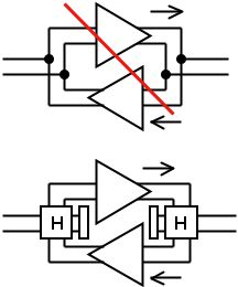
A gyrator is a passive, linear, lossless, two-port electrical network element proposed in 1948 by Bernard D. H. Tellegen as a hypothetical fifth linear element after the resistor, capacitor, inductor and ideal transformer. Unlike the four conventional elements, the gyrator is non-reciprocal. Gyrators permit network realizations of two-(or-more)-port devices which cannot be realized with just the conventional four elements. In particular, gyrators make possible network realizations of isolators and circulators. Gyrators do not however change the range of one-port devices that can be realized. Although the gyrator was conceived as a fifth linear element, its adoption makes both the ideal transformer and either the capacitor or inductor redundant. Thus the number of necessary linear elements is in fact reduced to three. Circuits that function as gyrators can be built with transistors and op-amps using feedback.

An antenna tuner is an electronic device insered into the feedline between a radio transmitter and its antenna. Its purpose is to optimize power transfer by matching the impedance of the radio to the impedance of the end of the feedline connecting the antenna to the transmitter.
The input impedance of an electrical network is the measure of the opposition to current (impedance), both static (resistance) and dynamic (reactance), into the load that is external to the electrical source network. The input admittance is a measure of the load network's propensity to draw current. The source network is the portion of the network that transmits power, and the load network is the portion of the network that consumes power.

In analog telephony, a telephone hybrid is the component at the ends of a subscriber line of the public switched telephone network (PSTN) that converts between two-wire and four-wire forms of bidirectional audio paths. When used in broadcast facilities to enable the airing of telephone callers, the broadcast-quality telephone hybrid is known as a broadcast telephone hybrid or telephone balance unit.

An autotransformer is an electrical transformer with only one winding. The "auto" prefix refers to the single coil acting alone, not to any kind of automatic mechanism. In an autotransformer, portions of the same winding act as both the primary winding and secondary winding sides of the transformer. In contrast, an ordinary transformer has separate primary and secondary windings which have no metallic conducting path between them.
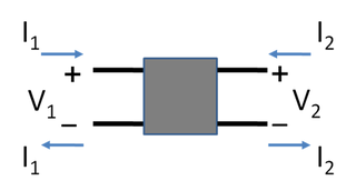
In electronics, a two-port network is an electrical network or device with two pairs of terminals to connect to external circuits. Two terminals constitute a port if the currents applied to them satisfy the essential requirement known as the port condition: the current entering one terminal must equal the current emerging from the other terminal on the same port. The ports constitute interfaces where the network connects to other networks, the points where signals are applied or outputs are taken. In a two-port network, often port 1 is considered the input port and port 2 is considered the output port.
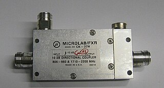
Power dividers and directional couplers are passive devices used mostly in the field of radio technology. They couple a defined amount of the electromagnetic power in a transmission line to a port enabling the signal to be used in another circuit. An essential feature of directional couplers is that they only couple power flowing in one direction. Power entering the output port is coupled to the isolated port but not to the coupled port. A directional coupler designed to split power equally between two ports is called a hybrid coupler.

A variety of types of electrical transformer are made for different purposes. Despite their design differences, the various types employ the same basic principle as discovered in 1831 by Michael Faraday, and share several key functional parts.
A balanced circuit is circuitry for use with a balanced line or the balanced line itself. Balanced lines are a common method of transmitting many types of electrical communication signals between two points on two wires. In a balanced line the two signal lines are of a matched impedance to help ensure that interference induced in the line is common-mode and can be removed at the receiving end by circuitry with good common-mode rejection. To maintain the balance, circuit blocks which interface to the line, or are connected in the line, must also be balanced.
Nominal impedance in electrical engineering and audio engineering refers to the approximate designed impedance of an electrical circuit or device. The term is applied in a number of different fields, most often being encountered in respect of:
In control system theory, and various branches of engineering, a transfer function matrix, or just transfer matrix is a generalisation of the transfer functions of single-input single-output (SISO) systems to multiple-input and multiple-output (MIMO) systems. The matrix relates the outputs of the system to its inputs. It is a particularly useful construction for linear time-invariant (LTI) systems because it can be expressed in terms of the s-plane.
This glossary of electrical and electronics engineering is a list of definitions of terms and concepts related specifically to electrical engineering and electronics engineering. For terms related to engineering in general, see Glossary of engineering.