
Code-division multiple access (CDMA) is a channel access method used by various radio communication technologies. CDMA is an example of multiple access, where several transmitters can send information simultaneously over a single communication channel. This allows several users to share a band of frequencies. To permit this without undue interference between the users, CDMA employs spread spectrum technology and a special coding scheme.

Time-division multiple access (TDMA) is a channel access method for shared-medium networks. It allows several users to share the same frequency channel by dividing the signal into different time slots. The users transmit in rapid succession, one after the other, each using its own time slot. This allows multiple stations to share the same transmission medium while using only a part of its channel capacity. Dynamic TDMA is a TDMA variant that dynamically reserves a variable number of time slots in each frame to variable bit-rate data streams, based on the traffic demand of each data stream.
The Universal Mobile Telecommunications System (UMTS) is a 3G mobile cellular system for networks based on the GSM standard. Developed and maintained by the 3GPP, UMTS is a component of the International Telecommunication Union IMT-2000 standard set and compares with the CDMA2000 standard set for networks based on the competing cdmaOne technology. UMTS uses wideband code-division multiple access (W-CDMA) radio access technology to offer greater spectral efficiency and bandwidth to mobile network operators.
In telecommunications and computer networking, multiplexing is a method by which multiple analog or digital signals are combined into one signal over a shared medium. The aim is to share a scarce resource – a physical transmission medium. For example, in telecommunications, several telephone calls may be carried using one wire. Multiplexing originated in telegraphy in the 1870s, and is now widely applied in communications. In telephony, George Owen Squier is credited with the development of telephone carrier multiplexing in 1910.
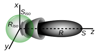
In electromagnetics, an antenna's gain is a key performance parameter which combines the antenna's directivity and radiation efficiency. The term power gain has been deprecated by IEEE. In a transmitting antenna, the gain describes how well the antenna converts input power into radio waves headed in a specified direction. In a receiving antenna, the gain describes how well the antenna converts radio waves arriving from a specified direction into electrical power. When no direction is specified, gain is understood to refer to the peak value of the gain, the gain in the direction of the antenna's main lobe. A plot of the gain as a function of direction is called the antenna pattern or radiation pattern. It is not to be confused with directivity, which does not take an antenna's radiation efficiency into account.
In the seven-layer OSI model of computer networking, the physical layer or layer 1 is the first and lowest layer: the layer most closely associated with the physical connection between devices. The physical layer provides an electrical, mechanical, and procedural interface to the transmission medium. The shapes and properties of the electrical connectors, the frequencies to transmit on, the line code to use and similar low-level parameters, are specified by the physical layer.
In telecommunications and computer networks, a channel access method or multiple access method allows more than two terminals connected to the same transmission medium to transmit over it and to share its capacity. Examples of shared physical media are wireless networks, bus networks, ring networks and point-to-point links operating in half-duplex mode.

In radio engineering, an antenna or aerial is an electronic device that converts an alternating electric current into radio waves (transmitting), or radio waves into an electric current (receiving). It is the interface between radio waves propagating through space and electric currents moving in metal conductors, used with a transmitter or receiver. In transmission, a radio transmitter supplies an electric current to the antenna's terminals, and the antenna radiates the energy from the current as electromagnetic waves. In reception, an antenna intercepts some of the power of a radio wave in order to produce an electric current at its terminals, that is applied to a receiver to be amplified. Antennas are essential components of all radio equipment.

Interim Standard 95 (IS-95) was the first digital cellular technology that used code-division multiple access (CDMA). It was developed by Qualcomm and later adopted as a standard by the Telecommunications Industry Association in TIA/EIA/IS-95 release published in 1995. The proprietary name for IS-95 is cdmaOne.
Frequency-division multiple access (FDMA) is a channel access method used in some multiple-access protocols. FDMA allows multiple users to send data through a single communication channel, such as a coaxial cable or microwave beam, by dividing the bandwidth of the channel into separate non-overlapping frequency sub-channels and allocating each sub-channel to a separate user. Users can send data through a subchannel by modulating it on a carrier wave at the subchannel's frequency. It is used in satellite communication systems and telephone trunklines.
In IEEE 802 LAN/MAN standards, the medium access control (MAC), also called media access control, is the layer that controls the hardware responsible for interaction with the wired or wireless transmission medium. The MAC sublayer and the logical link control (LLC) sublayer together make up the data link layer. The LLC provides flow control and multiplexing for the logical link, while the MAC provides flow control and multiplexing for the transmission medium.

Effective radiated power (ERP), synonymous with equivalent radiated power, is an IEEE standardized definition of directional radio frequency (RF) power, such as that emitted by a radio transmitter. It is the total power in watts that would have to be radiated by a half-wave dipole antenna to give the same radiation intensity as the actual source antenna at a distant receiver located in the direction of the antenna's strongest beam. ERP measures the combination of the power emitted by the transmitter and the ability of the antenna to direct that power in a given direction. It is equal to the input power to the antenna multiplied by the gain of the antenna. It is used in electronics and telecommunications, particularly in broadcasting to quantify the apparent power of a broadcasting station experienced by listeners in its reception area.
A cellular network or mobile network is a telecommunications network where the link to and from end nodes is wireless and the network is distributed over land areas called cells, each served by at least one fixed-location transceiver. These base stations provide the cell with the network coverage which can be used for transmission of voice, data, and other types of content. A cell typically uses a different set of frequencies from neighboring cells, to avoid interference and provide guaranteed service quality within each cell.
Spectral efficiency, spectrum efficiency or bandwidth efficiency refers to the information rate that can be transmitted over a given bandwidth in a specific communication system. It is a measure of how efficiently a limited frequency spectrum is utilized by the physical layer protocol, and sometimes by the medium access control.
In signal processing, direction of arrival (DOA) denotes the direction from which usually a propagating wave arrives at a point, where usually a set of sensors are located. These set of sensors forms what is called a sensor array. Often there is the associated technique of beamforming which is estimating the signal from a given direction. Various engineering problems addressed in the associated literature are:
Orthogonal frequency-division multiple access (OFDMA) is a multi-user version of the popular orthogonal frequency-division multiplexing (OFDM) digital modulation scheme. Multiple access is achieved in OFDMA by assigning subsets of subcarriers to individual users. This allows simultaneous low-data-rate transmission from several users.
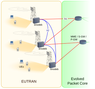
E-UTRA is the air interface of 3rd Generation Partnership Project (3GPP) Long Term Evolution (LTE) upgrade path for mobile networks. It is an acronym for Evolved UMTS Terrestrial Radio Access, also known as the Evolved Universal Terrestrial Radio Access in early drafts of the 3GPP LTE specification. E-UTRAN is the combination of E-UTRA, user equipment (UE), and a Node B.

This is a comparison of standards of wireless networking technologies for devices such as mobile phones. A new generation of cellular standards has appeared approximately every tenth year since 1G systems were introduced in 1979 and the early to mid-1980s.

Opportunity-Driven Multiple Access (ODMA) is a UMTS communications relaying protocol standard first introduced by the European Telecommunication Standards Institute (ETSI) in 1996. ODMA has been adopted by the 3rd-Generation Partnership Project, 3GPP to improve the efficiency of UMTS networks using the TDD mode. One of the objectives of ODMA is to enhance the capacity and the coverage of radio transmissions towards the boundaries of the cell. While mobile stations under the cell coverage area can communicate directly with the base station, mobile stations outside the cell boundary can still access the network and communicating with the base station via multihop transmission. Mobile stations with high data rate inside the cell are used as multihop relays.
In radio systems, many different antenna types are used whose properties are especially crafted for particular applications.