Supply energy using single wire with earth as return
This article is about power distribution. For the telecommunications use, see earth-return telegraph.
HVDC SWER power line in Cahora Bassa (Mozambique / South Africa)
Single-wire earth return (SWER) or single-wire ground return is a single-wire transmission line which supplies single-phase electric power from an electrical grid to remote areas at lowest cost. The earth (or sometimes a body of water) is used as the return path for the current, to avoid the need for a second wire (or neutral wire) to act as a return path.
Single-wire earth return is principally used for rural electrification, but also finds use for larger isolated loads such as water pumps. It is also used for high-voltage direct current over submarine power cables. Electric single-phase railway traction, such as light rail, uses a very similar system. It uses resistors to earth to reduce hazards from rail voltages, but the primary return currents are through the rails.[1]
History
Telegraph circuits from the 1840s used a single wire on poles per circuit and the ground to form a closed circuit. Early telephone circuits were also unbalanced lines, but later were converted to 2 wires per circuit, to form a balanced line system, which was less affected by electromagnetic interference.
In 1897, Nikola Tesla patented a high voltage AC transmission and distribution system using a single wire and ground electrodes. From the 1890s and early 1900s, several power companies used the ground instead of the neutral wire to save copper and aluminium.
Lloyd Mandeno, OBE (1888–1973) fully developed SWER in New Zealand around 1925 for rural electrification. Although he termed it "Earth Working Single Wire Line", it was often called "Mandeno’s Clothesline".[2] More than 200,000 kilometres (100,000 miles) have now been installed in Australia and New Zealand. It is considered safe, reliable and low-cost, provided that safety features and earthing are correctly installed. The Australian standards are widely used and cited. It has been applied around the world, such as in the Canadian province of Saskatchewan; Brazil; Africa; and portions of the United States' Upper Midwest and Alaska (Bethel).
Operating principle
SWER is a viable choice for a distribution system when conventional return current wiring would cost more than SWER's isolation transformers and small power losses. Power engineers experienced with both SWER and conventional power lines rate SWER as equally safe, more reliable, less costly, but with slightly lower efficiency than conventional lines.[3] SWER can cause fires when maintenance is poor, and bushfire is a risk.[4]
Schematic of SWER. Power flows from source on left to destination on right.
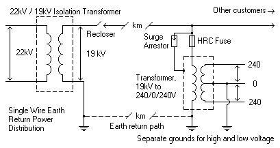
Power is supplied to the SWER line by an isolating transformer of up to 300kVA. This transformer isolates the grid from ground or earth. The voltage changes due to the transition from line-to-line to line-to-earth, typically reducing a 22kV grid to 12.7kV SWER or a 33kV grid to 19.1kV SWER.
The SWER line is a single conductor that may stretch for tens or even hundreds of kilometres (miles), with a number of distribution transformers along its length. At each transformer, such as a customer's premises, current flows from the line, through the primary coil of a step-down isolation transformer, to earth through an earth stake. From the earth stake, the current eventually finds its way back to the main step-up transformer at the head of the line, completing the circuit.[3] SWER is therefore a practical example of a phantom loop.
In areas with higher-resistance soil, the grounding rod can float to higher voltages, wasting energy. The resistance may be high enough to affect self-resetting circuit breakers, which usually reset due to a difference in voltage between line and neutral. With dry, high-resistance soils, the reduced difference in voltage between line and neutral may prevent breakers from resetting. In Australia, locations with very dry soils need the grounding rods to be extra deep.[5] Experience in Alaska shows that SWER needs to be grounded below permafrost, which is high-resistance.[6]
The secondary winding of the local transformer will supply the customer with either single ended single phase (N-0) or split-phase (N-0-N) power in the region's standard appliance voltages, with the 0volt line connected to a safety earth that does not normally carry an operating current.
A large SWER line may feed as many as 80 distribution transformers. The transformers are usually rated at 5kVA, 10kVA, and 25kVA. The load densities are usually below 0.5kVA per kilometer (0.8kVA per mile) of line. Any single customer's maximum demand will typically be less than 3.5kVA, but larger loads up to the capacity of the distribution transformer can also be supplied.
Some SWER systems in the USA are conventional distribution feeders that were built without a continuous neutral (some of which were obsolete transmission lines that were refitted for rural distribution service). The substation feeding such lines has a grounding rod on each pole within the substation; then on each branch from the line, the span between the pole next to and the pole carrying the transformer would have a grounded conductor (giving each transformer two grounding points for safety reasons).
Mechanical design
Proper mechanical design of a SWER line can lower its lifetime cost and increase its safety.
Since the line is high voltage, with small currents, the conductor used in historic SWER lines was Number-8 galvanized steel fence wire. More modern installations use specially designed AS1222.1[7][8]high-carbon steel, aluminum-clad wires. Aluminum clad wires corrode in coastal areas, but are otherwise more suitable.[9] Because of the long spans and high mechanical tensions, vibration from wind can cause damage to the wires. Modern systems install spiral vibration dampers on the wires.[9]
Insulators are often porcelain because polymers are prone to ultraviolet damage. Some utilities install higher-voltage insulators so the line can be easily upgraded to carry more power. For example, 12 kV lines may be insulated to 22 kV, or 19 kV lines to 33 kV.[9]
Reinforced concrete poles have been traditionally used in SWER lines because of their low cost, low maintenance, and resistance to water damage, termites and fungi. Local labor can produce them in most areas, further lowering costs. In New Zealand, metal poles are common (often being former rails from a railway line). Wooden poles are acceptable. In Mozambique, poles had to be at least 12m (39ft) high to permit safe passage of giraffes beneath the lines.[9]
If an area is prone to lightning, modern designs place lightning ground straps in the poles when they are constructed, before erection. The straps and wiring can be arranged to be a low-cost lightning arrestor with rounded edges to avoid attracting a lightning strike.[9]
SWER is promoted as safe due to isolation of the ground from both the generator and user. Most other electrical systems use a metallic neutral connected directly to the generator or a shared ground.[3]
Grounding is critical. Significant currents on the order of 8amperes flow through the ground near the earth points. A good-quality earth connection is needed to prevent risk of electric shock due to earth potential rise near this point. Separate grounds for power and safety are also used. Duplication of the ground points assures that the system is still safe if either of the grounds is damaged.
A good earth connection is normally a 6metre (20 foot) stake of copper-clad steel driven vertically into the ground, and bonded to the transformer earth and tank. A good ground resistance is 5–10 ohms which can be measured using specialist earth test equipment. SWER systems are designed to limit the electric field in the earth to 20 volts per meter to avoid shocking people and animals that might be in the area.
Other standard features include automatic reclosing circuit breakers (reclosers). Most faults (overcurrent) are transient. Since the network is rural, most of these faults will be cleared by the recloser. Each service site needs a rewirable drop out fuse for protection and switching of the transformer. The transformer secondary should also be protected by a standard high-rupture capacity (HRC) fuse or low voltage circuit breaker. A surge arrestor (spark gap) on the high voltage side is common, especially in lightning-prone areas.
Most fire safety hazards in electrical distribution are from aging equipment: corroded lines, broken insulators, etc. The lower cost of SWER maintenance can reduce the cost of safe operation in these cases.[4]
SWER avoids lines clashing in wind, a substantial fire-safety feature,[4] but a problem surfaced in the official investigation into the Black Saturday bushfires in Victoria, Australia. These demonstrated that a broken SWER conductor can short to ground across a resistance similar to the circuit's normal load; in that particular case, a tree. This can cause large currents without a ground-fault indication.[4] This can present a danger in fire-prone areas where a conductor may snap and current may arc through trees or dry grass.
Bare-wire or ground-return telecommunications can be compromised by the ground-return current if the grounding area is closer than 100metres (yards) or sinks more than 10A of current. Modern radio, optic fibre channels, and cell phone systems are unaffected.
Many national electrical regulations (notably the U.S.) require a metallic return line from the load to the generator.[10] In these jurisdictions, each SWER line must be approved by exception.
Cost advantages
SWER's main advantage is its low cost. It is often used in sparsely populated areas where the cost of building an isolated distribution line cannot be justified. Capital costs are roughly 50% of an equivalent two-wire single-phase line. They can cost 30% of 3-wire three-phase systems. Maintenance costs are roughly 50% of an equivalent three phase line.
SWER also reduces the largest cost of a distribution network: the number of poles. Conventional 2-wire or 3-wire distribution lines have a higher power transfer capacity, but can require 7 poles per kilometre (12 poles per mile), with spans of 100 to 150 metres (110 to 160 yards). SWER's high line voltage and low current also permits the use of low-cost galvanized steel wire (historically, No. 8 fence wire).[9] Steel's greater strength permits spans of 400 metres (¼ mile) or more, reducing the number of poles to 2.5 per kilometre (4 per mile).
If the poles also carry optical fiber cable for telecommunications (metal conductors may not be used), capital expenditures by the power company may be further reduced.
Reliability
SWER can be used in a grid or loop, but is usually arranged in a linear or radial layout to save costs. In the customary linear form, a single-point failure in a SWER line causes all customers further down the line to lose power. However, since it has fewer components in the field, SWER has less to fail. For example, since there is only one line, winds can't cause lines to clash, removing a source of damage, as well as a source of rural bush fires.
Since the bulk of the transmission line has low resistance attachments to earth, excessive ground currents from shorts and geomagnetic storms are more rare than in conventional metallic-return systems. So, SWER has fewer ground-fault circuit-breaker openings to interrupt service.[3]
Upgradeability
A well-designed SWER line can be substantially upgraded as demand grows without new poles.[11] The first step may be to replace the steel wire with more expensive copper-clad or aluminum-clad steel wire.
It may be possible to increase the voltage. Some distant SWER lines now operate at voltages as high as 35 kV. Normally this requires changing the insulators and transformers, but no new poles are needed.[12]
If more capacity is needed, a second SWER line can be run on the same poles to provide two SWER lines 180degrees out of phase. This requires more insulators and wire, but doubles the power without doubling the poles. Many standard SWER poles have several bolt holes to support this upgrade. This configuration causes most ground currents to cancel, reducing shock hazards and interference with communication lines.
Two-phase service is also possible with a two-wire upgrade:[citation needed][discuss] Though less reliable, it is more efficient. As more power is needed, the lines can be upgraded to match the load, from single wire SWER to two wire, single phase and finally to three wire, three phase. This ensures a more efficient use of capital and makes the initial installation more affordable.
Customer equipment installed before these upgrades will all be single phase, and can be reused after the upgrade. If small amounts of three-phase power are needed, it can be economically synthesized from two-phase power with on-site equipment.
Power-quality weakness
SWER lines tend to be long, with high impedance, so the voltage drop along the line is often a problem, causing poor regulation. Variations in demand cause variation in the delivered voltage. To combat this, some installations have automatic variable transformers at the customer site to keep the received voltage within legal specifications.[13]
After some years of experience, the inventor advocated a capacitor in series with the ground of the main isolation transformer to counteract the inductive reactance of the transformers, wire and earth return path. The plan was to improve the power factor, reduce losses and improve voltage performance due to reactive power flow.[3] Though theoretically sound, this is not standard practice. It does also allow the use of a DC test loop, to distinguish a legitimate variable load from (for example) a fallen tree, which would be a DC path to ground.
Use
Single-wire earth return is used throughout the globe, most commonly in New Zealand and Australia.
Colombia
SWER systems are forbidden for national electric regulation RETIE (REGLAMENTO DE INSTALACIONES ELECTRICAS).
United States
Alaska
In 1981 a high-power 8.5mile prototype SWER line was successfully installed from a diesel plant in Bethel to Napakiak in Alaska, United States. It operates at 80kV, and was originally installed on special lightweight fiberglass poles that formed an A-frame. Since then, the A frames have been removed and standard wooden power poles were installed. The A-framed poles could be carried on lightweight snow machines, and could be installed with hand tools on permafrost without extensive digging. Erection of "anchoring" poles still required heavy machinery, but the cost savings were significant.
Researchers at the University of Alaska Fairbanks, United States estimate that a network of such lines, combined with coastal wind turbines, could substantially reduce rural Alaska's dependence on increasingly expensive diesel fuel for power generation.[14] Alaska's state economic energy screening survey advocated further study of this option to use more of the state's underutilized power sources.[15]
Many high-voltage direct current systems (HVDC) using submarine power cables are single wire earth return systems. Bipolar systems with both positive and negative cables may also retain a seawater grounding electrode, used when one pole has failed. To avoid electrochemical corrosion, the ground electrodes of such systems are situated apart from the converter stations and not near the transmission cable.
The electrodes can be situated in the sea or on land. Bare copper wires can be used for cathodes, and graphite rods buried in the ground, or titanium grids in the sea are used for anodes. To avoid electrochemical corrosion (and passivation of titanium surfaces) the current density at the surface of the electrodes must be small, and therefore large electrodes are required.
Examples of HVDC systems with single wire earth return include the Baltic Cable and Kontek.
Installations
The following table shows various installations of SWER systems
↑ Service experience with single wire earth return distribution systems in central Queensland. 7th CEPSI conference. Brisbane, Australia. 15–22 October 1988.
1 2 3 4 5 6 7 Power to the People Describes use of SWER in the rural electrification of Mozambique. Transmission & Distribution World, 2009. Accessed 2011-8-10
Distributed generation as voltage support for single wire earth return systems, Kashem, M.A.; Ledwich, G.; IEEE Transactions on Power Delivery, Volume 19, Issue 3, July 2004 Page(s): 1002–1011
This page is based on this Wikipedia article Text is available under the CC BY-SA 4.0 license; additional terms may apply. Images, videos and audio are available under their respective licenses.