Numerical relay

Last updated
Protective relay Protective relay.jpg
Protective relay

In utility and industrial electric power transmission and distribution systems, a numerical relay is a computer-based system with software-based protection algorithms for the detection of electrical faults. [1] Such relays are also termed as microprocessor type protective relays. They are functional replacements for electro-mechanical protective relays and may include many protection functions in one unit, as well as providing metering, communication, and self-test functions.

Contents

Description and definition

The digital protective relay is a protective relay that uses a microprocessor to analyze power system voltages, currents or other process quantities for the purpose of detection of faults in an electric power system or industrial process system. A digital protective relay may also be called a "numeric protective relay". It is also called numerical relay.

Input processing

Low voltage and low current signals (i.e., at the secondary of a voltage transformers and current transformers) are brought into a low pass filter that removes frequency content above about 1/3 of the sampling frequency (a relay A/D converter needs to sample faster than twice per cycle of the highest frequency that it is to monitor). The AC signal is then sampled by the relay's analog-to-digital converter from 4 to 64 (varies by relay) samples per power system cycle. As a minimum, magnitude of the incoming quantity, commonly using Fourier transform concepts (RMS and some form of averaging) would be used in a simple relay function. More advanced analysis can be used to determine phase angles, power, reactive power, impedance, waveform distortion, and other complex quantities.

Only the fundamental component is needed for most protection algorithms, unless a high speed algorithm is used that uses subcycle data to monitor for fast changing issues. The sampled data is then passed through a low pass filter that numerically removes the frequency content that is above the fundamental frequency of interest (i.e., nominal system frequency), and uses Fourier transform algorithms to extract the fundamental frequency magnitude and angle.

Logic processing

The relay analyzes the resultant A/D converter outputs to determine if action is required under its protection algorithm(s). Protection algorithms are a set of logic equations in part designed by the protection engineer, and in part designed by the relay manufacturer. The relay is capable of applying advanced logic. It is capable of analyzing whether the relay should trip or restrain from tripping based on parameters set by the user, compared against many functions of its analogue inputs, relay contact inputs, timing and order of event sequences.

If a fault condition is detected, output contacts operate to trip the associated circuit breaker(s).

Parameter setting

The logic is user-configurable and can vary from simply changing front panel switches or moving of circuit board jumpers to accessing the relay's internal parameter setting webpage via communications link on another computer hundreds of kilometers away.

The relay may have an extensive collection of settings, beyond what can be entered via front panel knobs and dials, and these settings are transferred to the relay via an interface with a PC (personal computer), and this same PC interface may be used to collect event reports from the relay.

Event recording

In some relays, a short history of the entire sampled data is kept for oscillographic records. The event recording would include some means for the user to see the timing of key logic decisions, relay I/O (input/output) changes, and see, in an oscillographic fashion, at least the fundamental component of the incoming analogue parameters.

Data display

Digital/numerical relays provide a front panel display, or display on a terminal through a communication interface. This is used to display relay settings and real-time current/voltage values, etc.

More complex digital relays will have metering and communication protocol ports, allowing the relay to become an element in a SCADA system. Communication ports may include RS232/RS485 or Ethernet (copper or fibre-optic). Communication languages may include Modbus, DNP3 or IEC61850 protocols.

Comparison with other types

Electromechanical protective relays at a hydroelectric generation station Protective Relays Hydroelectric Station.JPG
Electromechanical protective relays at a hydroelectric generation station

By contrast, an electromechanical protective relay converts the voltages and currents to magnetic and electric forces and torques that press against spring tensions in the relay. The tension of the spring and taps on the electromagnetic coils in the relay are the main processes by which a user sets such a relay.

In a solid-state relay, the incoming voltage and current wave-forms are monitored by analog circuits, not recorded or digitized. The analog values are compared to settings made by the user via potentiometers in the relay, and in some case, taps on transformers.

In some solid-state relays, a simple microprocessor does some of the relay logic, but the logic is fixed and simple. For instance, in some time overcurrent solid state relays, the incoming AC current is first converted into a small signal AC value, then the AC is fed into a rectifier and filter that converts the AC to a DC value proportionate to the AC waveform. An op-amp and comparator is used to create a DC that rises when a trip point is reached. Then a relatively simple microprocessor does a slow speed A/D conversion of the DC signal, integrates the results to create the time-overcurrent curve response, and trips when the integration rises above a set-point. Though this relay has a microprocessor, it lacks the attributes of a digital/numeric relay, and hence the term "microprocessor relay" is not a clear term.

History

The digital/numeric relay was invented by George Rockefeller. [2] George conceived of it in his Master's Thesis in 1967–68 at Newark College of Engineering. [3] He published his seminal paper Fault Protection with a Digital Computer [4] in 1969. Westinghouse developed the first digital relay with the Prodar 70 [5] being developed between 1969 and 1971. It was commissioned in service on a 230kV transmission line at PG&E's Tesla substation in February 1971 and was in service for six years. [6] In 2017, George received the IEEE Halperin Electric Transmission and Distribution Award. [7] The award was for "pioneering development and practical demonstration of protective relaying of electric power systems with real-time digital computer techniques." George was chairman of the IEEE Power System Relaying and Control (PSRC) committee (1981-1982) as well as a member of the "Computer Relaying Subcommittee" which was created by the PSRC in 1971 and disbanded in 1978. He wrote the foreword for the PSRC tutorial on Computer Relaying produced in 1979.

In 1971 M. Ramamoorty was the first to describe [8] calculation of impedance for distance protection using discrete Fourier analysis.

The first practical commercially available microprocessor based digital/numeric relay was made by Edmund O. Schweitzer, III in the early 1980s. SEL, AREVA, and ABB Group's were early forerunners making some of the early market advances in the arena, but the arena has become crowded today with many manufacturers. In transmission line and generator protection, by the mid-1990s the digital relay had nearly replaced the solid state and electro-mechanical relay in new construction. In distribution applications, the replacement by the digital relay proceeded a bit more slowly. While the great majority of feeder relays in new applications today are digital, the solid state relay still sees some use where simplicity of the application allows for simpler relays, which allows one to avoid the complexity of digital relays.

Protective element types

Protective elements refer to the overall logic surrounding the electrical condition that is being monitored. For instance, a differential element refers to the logic required to monitor two (or more) currents, find their difference, and trip if the difference is beyond certain parameters. The term element and function are quite interchangeable in many instances.

For simplicity on one-line diagrams, the protection function is usually identified by an ANSI device number. In the era of electromechanical and solid state relays, any one relay could implement only one or two protective functions, so a complete protection system may have many relays on its panel. In a digital/numeric relay, many functions are implemented by the microprocessor programming. Any one numeric relay may implement one or all of these functions.

A listing of device numbers is found at ANSI Device Numbers. A summary of some common device numbers seen in digital relays is:

See also

Related Research Articles

Relay Electrically-operated switch

A relay is an electrically operated switch. It consists of a set of input terminals for a single or multiple control signals, and a set of operating contact terminals. The switch may have any number of contacts in multiple contact forms, such as make contacts, break contacts, or combinations thereof.

Ground (electricity) Reference point in an electrical circuit from which voltages are measured

In electrical engineering, ground or earth is a reference point in an electrical circuit from which voltages are measured, a common return path for electric current, or a direct physical connection to the ground.

Circuit breaker Automatic circuit protection device

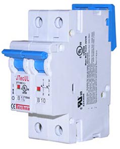
A circuit breaker is an electrical safety device designed to protect an electrical circuit from damage caused by an overcurrent or short circuit. Its basic function is to interrupt current flow to protect equipment and to prevent the risk of fire. Unlike a fuse, which operates once and then must be replaced, a circuit breaker can be reset to resume normal operation.

Electrical substation Part of an electrical generation, transmission, and distribution system

A substation is a part of an electrical generation, transmission, and distribution system. Substations transform voltage from high to low, or the reverse, or perform any of several other important functions. Between the generating station and consumer, electric power may flow through several substations at different voltage levels. A substation may include transformers to change voltage levels between high transmission voltages and lower distribution voltages, or at the interconnection of two different transmission voltages.

Surge protector Protects electrical devices from voltage spikes

A surge protector (or spike suppressor, surge suppressor, surge diverter, surge protection device or transient voltage surge suppressor is an appliance or device intended to protect electrical devices from voltage spikes in alternating current circuits. A voltage spike is a transient event, typically lasting 1 to 30 microseconds, that may reach over 1,000 volts. Lightning that hits a power line can give a spike of over 100,000 volts and can burn through wiring insulation and cause fires, but even modest spikes can destroy a wide variety of electronic devices, computers, battery chargers, modems and TVs etc, that happen to be plugged in at the time. Typically the surge device will trigger at a set voltage, around 3 to 4 times the mains voltage, and divert the current to earth. Some devices may absorb the spike and release it as heat. They are generally rated according to the amount of energy in joules they can absorb.

Current transformer Transformer used to scale alternating current, used as sensor for AC power

A current transformer (CT) is a type of transformer that is used to reduce or multiply an alternating current (AC). It produces a current in its secondary which is proportional to the current in its primary.

Recloser

In electric power distribution, automatic circuit reclosers (ACRs) are a class of switchgear which is designed for use on overhead electricity distribution networks to detect and interrupt momentary faults. Also known as reclosers or autoreclosers, ACRs are essentially high voltage rated circuit breakers with 11Kv or integrated current and voltage sensors and a protection relay, optimized for use as an overhead network distribution protection asset. Commercial ACRs are governed by the ANSI/IEEE C37.60, IEC 62271-111 and IEC 62271-200 standards. The three major classes of operating voltage are 15.5 kV, 27 kV and 38 kV.

Electronic component Discrete device in an electronic system

An electronic component is any basic discrete device or physical entity in an electronic system used to affect electrons or their associated fields. Electronic components are mostly industrial products, available in a singular form and are not to be confused with electrical elements, which are conceptual abstractions representing idealized electronic components and elements.

Power-system automation is the act of automatically controlling the power system via instrumentation and control devices. Substation automation refers to using data from Intelligent electronic devices (IED), control and automation capabilities within the substation, and control commands from remote users to control power-system devices.

This is an alphabetical list of articles pertaining specifically to electrical and electronics engineering. For a thematic list, please see List of electrical engineering topics. For a broad overview of engineering, see List of engineering topics. For biographies, see List of engineers.

Intelligent electronic device

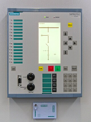
In the electric power industry, an intelligent electronic device (IED) is an integrated microprocessor-based controller of power system equipment, such as circuit breakers, transformers and capacitor banks.

Power system protection is a branch of electrical power engineering that deals with the protection of electrical power systems from faults through the disconnection of faulted parts from the rest of the electrical network. The objective of a protection scheme is to keep the power system stable by isolating only the components that are under fault, whilst leaving as much of the network as possible still in operation. The devices that are used to protect the power systems from faults are called protection devices.

Arc flash Heat and light produced during an electrical arc fault

An arc flash is the light and heat produced as part of an arc fault, a type of electrical explosion or discharge that results from a connection through air to ground or another voltage phase in an electrical system.

In the design of electrical power systems, the ANSI standard device numbers identifies the features of a protective device such as a relay or circuit breaker. These types of devices protect electrical systems and components from damage when an unwanted event occurs, such as an electrical fault. Device numbers are used to identify the functions of devices shown on a schematic diagram. Function descriptions are given in the standard.

In an electric power system, a fault or fault current is any abnormal electric current. For example, a short circuit is a fault in which a live wire touches a neutral or ground wire. An open-circuit fault occurs if a circuit is interrupted by a failure of a current-carrying wire or a blown fuse or circuit breaker. In three-phase systems, a fault may involve one or more phases and ground, or may occur only between phases. In a "ground fault" or "earth fault", current flows into the earth. The prospective short-circuit current of a predictable fault can be calculated for most situations. In power systems, protective devices can detect fault conditions and operate circuit breakers and other devices to limit the loss of service due to a failure.

Electric power system Network of electrical component deployed to generate, transmit & distribute electricity

An electric power system is a network of electrical components deployed to supply, transfer, and use electric power. An example of a power system is the electrical grid that provides power to homes and industries within an extended area. The electrical grid can be broadly divided into the generators that supply the power, the transmission system that carries the power from the generating centers to the load centers, and the distribution system that feeds the power to nearby homes and industries.

COMTRADE is a file format for storing oscillography and status data related to transient power system disturbances.

Protective relay Relay device designed to trip a circuit breaker when a fault is detected

In electrical engineering, a protective relay is a relay device designed to trip a circuit breaker when a fault is detected. The first protective relays were electromagnetic devices, relying on coils operating on moving parts to provide detection of abnormal operating conditions such as over-current, overvoltage, reverse power flow, over-frequency, and under-frequency.

From 1929 to the late 1960s, large alternating current power systems were modelled and studied on AC network analyzers or transient network analyzers. These special-purpose analog computers were an outgrowth of the DC calculating boards used in the very earliest power system analysis. By the middle of the 1950s, fifty network analyzers were in operation. AC network analyzers were much used for power flow studies, short circuit calculations, and system stability studies, but were ultimately replaced by numerical solutions running on digital computers. While the analyzers could provide real-time simulation of events, with no concerns about numeric stability of algorithms, the analyzers were costly, inflexible, and limited in the number of buses and lines that could be simulated. Eventually powerful digital computers replaced analog network analyzers for practical calculations, but analog physical models for studying electrical transients are still in use.

This glossary of electrical and electronics engineering is a list of definitions of terms and concepts related specifically to electrical engineering and electronics engineering. For terms related to engineering in general, see Glossary of engineering.

References

  1. "Schweitzer Programmable Automation Controller". Schweitzer Engineering Laboratories. Archived from the original on 9 September 2015. Retrieved 21 November 2012.
  2. "George Dorwart Rockefeller - Engineering and Technology History Wiki". ethw.org. Retrieved 2019-02-13.
  3. Rockefeller, George D. (1968-05-31). "Fault protection with a digital computer". Theses. 88 (4): 438–464. Bibcode:1969ITPAS..88..438R. doi:10.1109/TPAS.1969.292466.
  4. Rockefeller, G.D. (1969). "Fault Protection with a Digital Computer". IEEE Transactions on Power Apparatus and Systems. 88 (4): 438–464. Bibcode:1969ITPAS..88..438R. doi:10.1109/TPAS.1969.292466.
  5. Rockefeller, G.D.; Udren, E.A.; Gilcrest, G.B. (1972). "High-Speed Distance Relaying Using a Digital Computer I - System Description". IEEE Transactions on Power Apparatus and Systems. 91 (3): 1235–1243. Bibcode:1972ITPAS..91.1235G. doi:10.1109/TPAS.1972.293482.
  6. Rockefeller, G.D.; Udren, E.A. (1972). "High-Speed Distance Relaying Using a Digital Computer II-Test Results". IEEE Transactions on Power Apparatus and Systems. 91 (3): 1244–1258. Bibcode:1972ITPAS..91.1244R. doi:10.1109/TPAS.1972.293483.
  7. "IEEE Herman Halperin Electric Transmission and Distribution Award".
  8. Ramamoorty, M. (1971). "A note on impedance measurement using digital computers". IEE-IERE Proceedings - India. 9 (6): 243. doi:10.1049/iipi.1971.0062.