In general mechanical terms, the word desmodromic is used to refer to mechanisms that have different controls for their actuation in different directions.
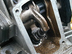
Desmodromic poppet valve in a Ducati engine
A desmodromic valve is a reciprocating engine poppet valve that is positively closed by a cam and leverage system, rather than by a more conventional spring.
The valves in a typical four-stroke engine allow the air/fuel mixture into the cylinder at the beginning of the cycle and exhaust spent gases at the end of the cycle. In a conventional four-stroke engine, valves are opened by a cam and closed by return spring. A desmodromic valve has two cams and two actuators, for positive opening and closing without a return spring.
Etymology
The word comes from the Greek words desmos (δεσμός, translated as "bond" or "knot") and dromos (δρόμος, "track" or "way"). This denotes the major characteristic of the valves being continuously "bound" to the camshaft.
Idea
The common valve spring system is satisfactory for traditional mass-produced engines that do not rev highly and are of a design that requires low maintenance.[1] At the period of initial desmodromic development, valve springs were a major limitation on engine performance because they would break from metal fatigue. In the 1950s new vacuum melt processes helped to remove impurities from the metal in valve springs, increasing their life and efficiency greatly. However, many springs would still fail at sustained operation above 8000 RPM.[2] The desmodromic system was devised to remedy this problem by completely removing the need for a spring. Furthermore, as maximum RPM increases, higher spring force is required to prevent valve float, leading to larger springs (with increased spring mass, and thus greater inertia), cam drag (as the valve springs require energy to compress, robbing the engine of power), and higher wear on the parts at all speeds, problems addressed by the desmodromic mechanism.
Design and history
Desmodromic poppet valve example
Fully controlled valve movement was conceived during the earliest days of engine development, but devising a system that worked reliably and was not overly complex took a long time. Desmodromic valve systems are first mentioned in patents in 1896 by Gustav Mees.[citation needed] Austin's marine engine of 1910 produced 300bhp and was installed in a speedboat called "Irene I"; its all-aluminium, twin-overhead-valve engine had twin magnetos, twin carburettors and desmodromic valves.[3] The 1914 Grand Prix Delage and Nagant (see Pomeroy "Grand Prix Car") used a desmodromic valve system (quite unlike the present day Ducati system).[4]
In 1925, Spanish engineer Wifredo Ricart obtained patent FR590149 for a similar valve drive mechanism.[5]
Azzariti, a short-lived Italian manufacturer from 1933 to 1934, produced 173cc and 348cc twin-cylinder engines, some of which had desmodromic valve gear, with the valve being closed by a separate camshaft.[6]
A later version of the Daimler-Benz inverted V12, like the 601 and 603X, the type that were used in the Messerschmitt Bf 109 (1930s), had desmodromic valves. [7]
In 1956, Fabio Taglioni, a Ducati engineer, developed a desmodromic valve system for the Ducati 125 Grand Prix, creating the Ducati 125 Desmo.
He was quoted:
The specific purpose of the desmodromic system is to force the valves to comply with the timing diagram as consistently as possible. In this way, any lost energy is negligible, the performance curves are more uniform and dependability is better.
The engineers that came after him continued that development, and Ducati held a number of patents relating to desmodromics. Desmodromic valve actuation has been applied to top-of-the-range production Ducati motorcycles since 1968, with the introduction of the "widecase" Mark 3 single cylinders.
In 1959 the Maserati brothers introduced one of their final designs: a desmodromic four-cylinder, 2000cc engine for their last O.S.C.A. Barchetta.
Comparison with conventional valvetrains
In modern engines, valve spring failure at high RPM has been mostly remedied. The main benefit of the desmodromic system is the prevention of valve float at high rpm.
In traditional spring-valve actuation, as engine speed increases, the inertia of the valve will eventually overcome the spring's ability to close it completely before the piston reaches top dead centre (TDC). This can lead to several problems. First, the valve does not completely return to its seat before combustion begins. This allows combustion gases to escape prematurely, leading to a reduction in cylinder pressure which causes a major decrease in engine performance. This can also overheat the valve, possibly warping it and leading to catastrophic failure. Second, and most damaging, the piston collides with the valve and both are destroyed. In spring-valve engines the traditional remedy for valve float is to stiffen the springs. This increases the seat pressure of the valve (the static pressure that holds the valve closed). This is beneficial at higher engine speeds because of a reduction in the aforementioned valve float. The drawback is increased forces on all valvetrain components and increased friction and associated temperature and wear. It does not decrease power because nearly all work put into compressing the spring is later released as the spring is allowed to uncompress.
The desmodromic system avoids some of the shortcomings of spring-loaded valves because it is not subject to the high loads associated with compressing stiff springs. However, it must still overcome the inertia of the valve itself, and that depends on the mass distribution of the moving parts. The effective mass of a traditional valve with spring includes one-half of the valve spring mass for symmetric springs and all of the valve spring retainer mass. However, a desmodromic system must deal with the inertia of the two rocker arms per valve, so this advantage depends greatly on the skill of the designer. Another disadvantage is the contact point between the cams and rocker arms. It is relatively easy to use roller tappets in conventional valvetrains, although it does add considerable moving mass. In a desmodromic system the roller would be needed at one end of the rocker arm, which would greatly increase its moment-of-inertia and negate its "effective mass" advantage. Thus, desmo systems have generally needed to deal with sliding friction between the cam and rocker arm and therefore may have greater wear. The contact points on most Ducati rocker arms are hard-chromed to reduce this wear. Another disadvantage is the difficulty in incorporating hydraulic valve lash adjusters to a desmodromic system; thus frequent valve clearance (lash) adjustments are required. Additionally, each valve requires two lash adjustments - one for the opening rocker and another for the closing rocker. However, it is rare for most high RPM engines with conventional spring-loaded valvetrains to incorporate hydraulic lash adjusters – so they too require periodic checks and adjustments of valve lash.
Before the days when valve drive dynamics could be analyzed by computer,[when?] desmodromic drive seemed to offer solutions for problems that were worsening with increasing engine speed. Since those days, lift, velocity, acceleration, and jerk curves for cams have been modelled by computer[8] to reveal that cam dynamics are not what they seemed. With proper analysis, problems relating to valve adjustment, hydraulic tappets, push rods, rocker arms, and above all, valve float, became things of the past without desmodromic drive.
Today[when?] most automotive engines use overhead cams, driving a flat tappet to achieve the shortest, lightest weight, and most inelastic path from cam to valve, thereby avoiding elastic elements such as pushrod and rocker arm. Computers have allowed for fairly accurate acceleration modelling of valve-train systems.
Before numerical computing methods were readily available, acceleration was only attainable by differentiating cam lift profiles twice, once for velocity and again for acceleration. This generates so much hash (noise) that the second derivative (acceleration) was uselessly inaccurate. Computers permitted integration from the jerk curve, the third derivative of lift, that is conveniently a series of contiguous straight lines whose vertices can be adjusted to give any desired lift profile.
Integration of the jerk curve produces a smooth acceleration curve while the third integral gives an essentially ideal lift curve (cam profile). With such cams, which mostly do not look like the ones "artists" formerly designed, valve noise (lift-off) went away and valve train elasticity came under scrutiny.
Today,[when?] most cams have mirror image (symmetric) profiles with identical positive and negative acceleration while opening and closing valves. However, some high speed (in terms of engine RPM) motors now employ asymmetrical cam profiles in order to quickly open valves and set them back in their seats more gently to reduce wear. As well, production vehicles have employed asymmetrical cam lobe profiles since the late 1940s, as seen in the 1948 Ford V8.[9] In this motor both the intake and exhaust profiles had an asymmetric design. More modern applications of asymmetrical camshafts include Cosworth's 2.3 liter crate motors, which use aggressive profiles to reach upwards of 280 brake horsepower.[10] An asymmetric cam either opens or closes the valves more slowly than it could, with the speed being limited by Hertzian contact stress between curved cam and flat tappet, thereby ensuring a more controlled acceleration of the combined mass of the reciprocating componentry (specifically the valve, tappet and spring).
In contrast, desmodromic drive uses two cams per valve, each with separate rocker arm (lever tappets). Maximum valve acceleration is limited by the cam-to-tappet galling stress, and therefore is governed by both the moving mass and the cam contact area. Maximum rigidity and minimum contact stress are best achieved with conventional flat tappets and springs whose lift and closure stress is unaffected by spring force; both occur at the base circle,[11] where spring load is minimum and contact radius is largest. Curved (lever) tappets[12] of desmodromic cams cause higher contact stress than flat tappets for the same lift profile, thereby limiting rate of lift and closure.
With conventional cams, stress is highest at full lift, when turning at zero speed (initiation of engine cranking), and diminishes with increasing speed as inertial force of the valve counters spring pressure, while a desmodromic cam has essentially no load at zero speed (in the absence of springs), its load being entirely inertial, and therefore increasing with speed. Its greatest inertial stress bears on its smallest radius. Acceleration forces for either method increase with the square of velocity resulting from kinetic energy.[13]
Valve float was analyzed and found to be caused largely by resonance in valve springs that generated oscillating compression waves among coils, much like a Slinky. High speed photography showed that at specific resonant speeds, valve springs were no longer making contact at one or both ends, leaving the valve floating[14] before crashing into the cam on closure.
For this reason, today[when?] as many as three concentric valve springs are sometimes nested inside one other; not for more force (the inner ones having no significant spring constant), but to act as snubbers to reduce oscillations in the outer spring.[citation needed]
An early solution[when?] to oscillating spring mass was the mousetrap or hairpin spring[15] used on Norton Manx[16] engines. These avoided resonance but were ungainly to locate inside cylinder heads.
Valve springs that do not resonate are progressive, wound with varying pitch or varying diameter called beehive springs[17] from their shape. The number of active coils in these springs varies during the stroke, the more closely wound coils being on the static end, becoming inactive as the spring compresses or as in the beehive spring, where the small diameter coils at the top are stiffer. Both mechanisms reduce resonance because spring force and its moving mass vary with stroke. This advance in spring design removed valve float, the initial impetus for desmodromic valve drive.
Examples
Ducati motocycle desmodromic valve timing engine parts: camshaft, valves, opening rocker arm and closing rocker arm
Ducati motorcycles with desmodromic valves have won numerous races and championships, including Superbike World Championships from 1990 to 1992, 1994–96, 1998–99, 2001, 2003–04, 2006, 2008 and 2011. Ducati's return to Grand Prix motorcycle racing was powered by a desmodromic V4 990cc engine in the GP3 (Desmosedici) bike, which went on to claim several victories, including a one-two finish at the final 990cc MotoGP race at Valencia, Spain in 2006. With the onset of the 800cc era in 2007, they are generally still considered to be the most powerful engines in the sport, and have powered Casey Stoner to the 2007 MotoGP Championship and Ducati to the constructors championship with the GP7 (Desmosedici) bike.
↑ Rivola, A., et al.: "Modelling the Elastodynamic Behaviour of a Desmodromic Valve Train", Proceedings of SMA2002 International Conference on Noise & Vibration Engineering,16–18 September 2002 - Leuven, Belgium
↑ Falco, Charles M. (July 2003). "The Art and Materials Science of 190mph Superbikes"(PDF). MRS Bulletin. p.514. Archived from the original(PDF) on 2007-03-07. Retrieved 2006-11-02. Thus, neglecting all other factors, the faster an engine can be made to turn, the more power can be generated. Unfortunately, through at least the 1950s, valve springs often would fatigue and break when engines were operated for significant periods of time much above 8000 rpm.
↑ Baker, John. "Austin Marine Engines". Austin Memories. Archived from the original on August 21, 2015. In 1910 Herbert Austin decided to build a Marine engine that at the time was very advanced. It produced 300bhp and was installed in a speedboat called "Irene I" which was named after his eldest daughter who had married Colonel Waite. The all aluminium twin ohv engine had twin magneto, twin carburettor and desmodronic valves.
This page is based on this Wikipedia article Text is available under the CC BY-SA 4.0 license; additional terms may apply. Images, videos and audio are available under their respective licenses.

