
In antenna theory, a phased array usually means an electronically scanned array, a computer-controlled array of antennas which creates a beam of radio waves that can be electronically steered to point in different directions without moving the antennas. The general theory of an electromagnetic phased array also finds applications in ultrasonic and medical imaging application and in optics optical phased array.

A waveguide is a structure that guides waves by restricting the transmission of energy to one direction. Common types of waveguides include acoustic waveguides which direct sound, optical waveguides which direct light, and radio-frequency waveguides which direct electromagnetic waves other than light like radio waves.
In electromagnetics, an evanescent field, or evanescent wave, is an oscillating electric and/or magnetic field that does not propagate as an electromagnetic wave but whose energy is spatially concentrated in the vicinity of the source. Even when there is a propagating electromagnetic wave produced, one can still identify as an evanescent field the component of the electric or magnetic field that cannot be attributed to the propagating wave observed at a distance of many wavelengths.
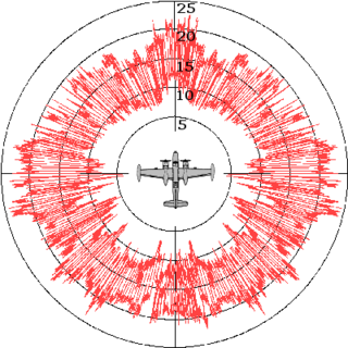
Radar cross-section (RCS), denoted σ, also called radar signature, is a measure of how detectable an object is by radar. A larger RCS indicates that an object is more easily detected.

A metamaterial is any material engineered to have a property that is rarely observed in naturally occurring materials. They are made from assemblies of multiple elements fashioned from composite materials such as metals and plastics. These materials are usually arranged in repeating patterns, at scales that are smaller than the wavelengths of the phenomena they influence. Metamaterials derive their properties not from the properties of the base materials, but from their newly designed structures. Their precise shape, geometry, size, orientation and arrangement gives them their smart properties capable of manipulating electromagnetic waves: by blocking, absorbing, enhancing, or bending waves, to achieve benefits that go beyond what is possible with conventional materials.

A sensor array is a group of sensors, usually deployed in a certain geometry pattern, used for collecting and processing electromagnetic or acoustic signals. The advantage of using a sensor array over using a single sensor lies in the fact that an array adds new dimensions to the observation, helping to estimate more parameters and improve the estimation performance. For example an array of radio antenna elements used for beamforming can increase antenna gain in the direction of the signal while decreasing the gain in other directions, i.e., increasing signal-to-noise ratio (SNR) by amplifying the signal coherently. Another example of sensor array application is to estimate the direction of arrival of impinging electromagnetic waves. The related processing method is called array signal processing. A third examples includes chemical sensor arrays, which utilize multiple chemical sensors for fingerprint detection in complex mixtures or sensing environments. Application examples of array signal processing include radar/sonar, wireless communications, seismology, machine condition monitoring, astronomical observations fault diagnosis, etc.

In electromagnetics, directivity is a parameter of an antenna or optical system which measures the degree to which the radiation emitted is concentrated in a single direction. It is the ratio of the radiation intensity in a given direction from the antenna to the radiation intensity averaged over all directions. Therefore, the directivity of a hypothetical isotropic radiator is 1, or 0 dBi.
Characteristic modes (CM) form a set of functions which, under specific boundary conditions, diagonalizes operator relating field and induced sources. Under certain conditions, the set of the CM is unique and complete (at least theoretically) and thereby capable of describing the behavior of a studied object in full.

A radio-frequency microelectromechanical system is a microelectromechanical system with electronic components comprising moving sub-millimeter-sized parts that provide radio-frequency (RF) functionality. RF functionality can be implemented using a variety of RF technologies. Besides RF MEMS technology, III-V compound semiconductor, ferrite, ferroelectric, silicon-based semiconductor, and vacuum tube technology are available to the RF designer. Each of the RF technologies offers a distinct trade-off between cost, frequency, gain, large-scale integration, lifetime, linearity, noise figure, packaging, power handling, power consumption, reliability, ruggedness, size, supply voltage, switching time and weight.

Metamaterial antennas are a class of antennas which use metamaterials to increase performance of miniaturized antenna systems. Their purpose, as with any electromagnetic antenna, is to launch energy into free space. However, this class of antenna incorporates metamaterials, which are materials engineered with novel, often microscopic, structures to produce unusual physical properties. Antenna designs incorporating metamaterials can step-up the antenna's radiated power.
Leaky-wave antenna (LWA) belong to the more general class of traveling wave antenna, that use a traveling wave on a guiding structure as the main radiating mechanism. Traveling-wave antenna fall into two general categories, slow-wave antennas and fast-wave antennas, which are usually referred to as leaky-wave antennas.

An antenna array is a set of multiple connected antennas which work together as a single antenna, to transmit or receive radio waves. The individual antennas are usually connected to a single receiver or transmitter by feedlines that feed the power to the elements in a specific phase relationship. The radio waves radiated by each individual antenna combine and superpose, adding together to enhance the power radiated in desired directions, and cancelling to reduce the power radiated in other directions. Similarly, when used for receiving, the separate radio frequency currents from the individual antennas combine in the receiver with the correct phase relationship to enhance signals received from the desired directions and cancel signals from undesired directions. More sophisticated array antennas may have multiple transmitter or receiver modules, each connected to a separate antenna element or group of elements.

The two-rays ground-reflection model is a multipath radio propagation model which predicts the path losses between a transmitting antenna and a receiving antenna when they are in line of sight (LOS). Generally, the two antenna each have different height. The received signal having two components, the LOS component and the reflection component formed predominantly by a single ground reflected wave.
A reconfigurable antenna is an antenna capable of modifying its frequency and radiation properties dynamically, in a controlled and reversible manner. In order to provide a dynamic response, reconfigurable antennas integrate an inner mechanism that enable the intentional redistribution of the RF currents over the antenna surface and produce reversible modifications of its properties. Reconfigurable antennas differ from smart antennas because the reconfiguration mechanism lies inside the antenna, rather than in an external beamforming network. The reconfiguration capability of reconfigurable antennas is used to maximize the antenna performance in a changing scenario or to satisfy changing operating requirements.

A frequency-selective surface (FSS) is any thin, repetitive surface designed to reflect, transmit or absorb electromagnetic fields based on the frequency of the field. In this sense, an FSS is a type of optical filter or metal-mesh optical filters in which the filtering is accomplished by virtue of the regular, periodic pattern on the surface of the FSS. Though not explicitly mentioned in the name, FSS's also have properties which vary with incidence angle and polarization as well - these are unavoidable consequences of the way in which FSS's are constructed. Frequency-selective surfaces have been most commonly used in the radio frequency region of the electromagnetic spectrum and find use in applications as diverse as the aforementioned microwave oven, antenna radomes and modern metamaterials. Sometimes frequency selective surfaces are referred to simply as periodic surfaces and are a 2-dimensional analog of the new periodic volumes known as photonic crystals.

High Resolution Wide Swath (HRWS) imaging is an important branch in synthetic aperture radar (SAR) imaging, a remote sensing technique capable of providing high resolution images independent of weather conditions and sunlight illumination. This makes SAR very attractive for the systematic observation of dynamic processes on the Earth's surface, which is useful for environmental monitoring, earth resource mapping and military systems.
In antenna theory, radiation efficiency is a measure of how well a radio antenna converts the radio-frequency power accepted at its terminals into radiated power. Likewise, in a receiving antenna it describes the proportion of the radio wave's power intercepted by the antenna which is actually delivered as an electrical signal. It is not to be confused with antenna efficiency, which applies to aperture antennas such as a parabolic reflector or phased array, or antenna/aperture illumination efficiency, which relates the maximum directivity of an antenna/aperture to its standard directivity.
The active reflection coefficient (ARC) is the reflection coefficient for a single antenna element in an array antenna, in the presence of mutual coupling. The active reflection coefficient is a function of frequency in addition to the excitation of the neighboring cells. In computational electromagnetics, the active reflection coefficient is usually determined from unit cell analysis in the frequency domain, where the phase shift over the unit cell is applied as a boundary condition. It has been suggested that the name "scan reflection coefficient" is more appropriate than "active reflection coefficient", however the latter remains the most commonly used name.
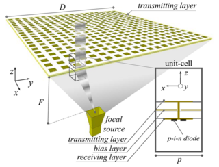
A transmitarray antenna is a phase-shifting surface (PSS), a structure capable of focusing electromagnetic radiation from a source antenna to produce a high-gain beam. Transmitarrays consist of an array of unit cells placed above a source (feeding) antenna. Phase shifts are applied to the unit cells, between elements on the receive and transmit surfaces, to focus the incident wavefronts from the feeding antenna. These thin surfaces can be used instead of a dielectric lens. Unlike phased arrays, transmitarrays do not require a feed network, so losses can be greatly reduced. Similarly, they have an advantage over reflectarrays in that feed blockage is avoided.
Nacer E. Chahat is a French Algerian-American engineer and researcher at the National Aeronautics and Space Administration (NASA) Jet Propulsion Laboratory.


