Transmitarray antenna

Last updated

Planar transmitarray fed by a horn antenna. Structure showing unit cells. Di palma txarray.png
Planar transmitarray fed by a horn antenna. Structure showing unit cells.

A transmitarray antenna (or just transmitarray or called as layered lens antenna [2] ) is a phase-shifting surface (PSS), a structure capable of focusing electromagnetic radiation from a source antenna to produce a high-gain beam. [3] Transmitarrays consist of an array of unit cells placed above a source (feeding) antenna. [4] Phase shifts are applied to the unit cells, between elements on the receive and transmit surfaces, to focus the incident wavefronts from the feeding antenna. [4] These thin surfaces can be used instead of a dielectric lens. Unlike phased arrays, transmitarrays do not require a feed network, so losses can be greatly reduced. [1] Similarly, they have an advantage over reflectarrays in that feed blockage is avoided. [5]

Contents

It is worth clarifying that transmitarrays can be used in both transmit and receive modes: the waves are transmitted through the structure in either direction. An important parameter in transmitarray design is the ratio, which determines the aperture efficiency. is the focal length and is the diameter of the transmitarray. The projected area of the feeding antenna determines the illumination efficiency of a transmitarray panel. Provided that the insertion loss of each unit cell is minimised, an aperture area appropriate to the feed radiation pattern can efficiently focus the wavefronts from the feed. [6]

Overview of techniques

Transmitarrays can be split into two types: fixed and reconfigurable. As described earlier, a transmitarray is a phase-shifting surface consisting of an array of unit cells. These focus the wavefronts from a feeding antenna into a narrower beamwidth. By applying a progressive phase shift across the aperture of the transmitarray, the beam can be focused and steered towards a direction away from boresight (0° angles).

Fixed transmitarrays

Ey-field component at a cross-section through a planar transmitarray consisting of double-square loop unit cells. The curvature of the outgoing wavefronts is reduced (the directivity is increased) compared to the incident wavefronts. Patch with double square loop PSS Ey field cross section.gif
Ey-field component at a cross-section through a planar transmitarray consisting of double-square loop unit cells. The curvature of the outgoing wavefronts is reduced (the directivity is increased) compared to the incident wavefronts.

First, consider fixed transmitarrays. At each location on the surface of the structure, the unit cells are physically scaled or rotated in order to obtain the required amplitude and phase distribution. Thus, only one focusing direction is available. The aim is to approximate the ideal phase distribution, such as for a feed located at , which can be achieved by discretising the surface of the transmitarray into several Fresnel zones. High aperture efficiency (55%) can be achieved at oblique angles of incidence using precision-machined double split ring slot unit cells. [7] A switched-beam transmitarray covering the 57 – 66 GHz band has been reported. [8] Three different types of unit cells were used, based on patches and coupling slots. Similarly, a 60 GHz design used unit cells with a 2-bit phase resolution and selected an optimal ratio to widen the bandwidth. [9] When = 0.5, a scan loss of 2.2 dB was achieved at a 30° steering angle.

Different types of unit cells have been used within the same transmitarray. In, [10] slot elements were placed near the centre of the transmitarray, as their polarisation performance is better at normal incidence, whereas double square ring slot elements were used at the edges, as they perform better at oblique incidence angles. This enabled the subtended (flare) angle of the feed horn to be increased, and hence the length of the horn, and the overall antenna size, to be reduced. Unit cells were not required at the centre of the transmitarray, where the phase shift was 0°. This reduced the insertion loss to around 1 dB at 105 GHz, as the majority of the beam amplitude was in the central region. In a different design, substrate integrated waveguide (SIW) aperture coupling was employed to reduce insertion losses and widen the bandwidth of a transmitarray operating at 140 GHz. [11] Due to the large number of vias required, this performance improvement was at the expense of a more complex and costly fabrication.

It has been shown that transmitarray implementation can be divided into two approaches: layered-scatterer and guided-wave. [12] The first approach uses multiple coupled layers to achieve a phase shift, but has poor sidelobe level (SLL) performance when steering due to higher-order Floquet modes. The second approach enables wider steering, at the expense of increased hardware cost and complexity.

Reconfiguration methods

In a reconfigurable transmitarray, the focusing direction is determined by electronically controlling the phase shift through each unit cell. [13] This enables the beam to be steered towards the user. Electronic reconfiguration can be achieved by several possible methods.

Radiation pattern for a planar transmitarray. Di Palma txarray rad patterns.png
Radiation pattern for a planar transmitarray.

PIN diodes can be used to enable fast phase reconfiguration with an insertion loss below 1 dB. [1] However, a large number of components is typically required, which increases the cost. A reconfigurable transmitarray, operating at 29 GHz with circular polarisation, has been demonstrated as a beamformer. [14] A boresight gain of 20.8 dBi was achieved, and the scan loss was 2.5 dB at 40°. Another implementation example is an active Fresnel reflectarray with control circuitry for the PIN diodes. [15] Although the unit cells were optimised, the scan loss was 3.4 dB at 30°. Reconfigurable near-field focusing can be implemented using slots containing PIN diodes. [16] By adjusting the phase compared to a reference wave, holographic principles enabled the use of a compact, planar feeding structure and suppression of undesired lobes. This was extended in [17] to an implementation of a Mills cross based on PIN diodes, in which an aperture was synthesised for imaging applications. Radial stubs were used to isolate the bias lines from the RF. By switching combinations of meta-elements on or off, the scan loss was 0 dB for steering angles of ±30°, but the total efficiency was only 35%.

In 2019, a transmitarray was fed by a planar phased array operating at 10 GHz, in order to achieve a high beam crossover gain level whilst maintaining an aperture efficiency of 57.5%. [18] The scan loss was 3.13 dB at ±30°. Similarly, a lens-enhanced phased array antenna, similar to a transmitarray, has been demonstrated. [19] By combining the beam steering capabilities of phased arrays and the focusing properties of transmitarrays, this hybrid antenna has a smaller form factor, [20] and steers to ±45° in both planes with a 3.2 dB increase in directivity at this angle. Its reconfigurable phase-shifting surface (PSS) contained micro-electro-mechanical (MEMS) switches to change the length of resonators, sandwiched within an antenna-filter-antenna structure. The PSS created the optimal 2D phase distribution needed to achieve high-gain beam focusing, but the MEMS fabrication process was complex and costly, requiring a large number of control lines. MEMS and other mechanical switching methods can achieve a relatively low insertion loss (2.5 dB) and an excellent linearity, but are prone to stiction and reliability issues [21]

Reconfigurable materials have shown promise for enabling a low-loss beam steering transmitarray. A vanadium dioxide reconfigurable metasurface operating at 100 GHz was presented in [22] using a crossed-slot unit cell. A heating element was used to thermally control the phase shift through each cell. The permittivity of liquid crystal (and hence the phase shift) can be reconfigured by applying a voltage between two parallel conducting plates. However, liquid crystal has several practical challenges. The liquid must be hermetically sealed in a cavity, and the crystal orientations aligned with the cavity walls in an unbiased state. The liquid can flow between cells, causing a variation in the RF properties of the transmitarray, and dynamic instabilities. [23] Liquid crystal reflectarrays have been extensively investigated at 78 GHz and 100 GHz. [24] [25] [26] In, [27] a fishnet metamaterial lens was designed, using liquid crystal to achieve a 360° electronically controlled phase range. The 5 dB unit cell insertion loss could be reduced by controlling the Bloch impedance (both and ) of each unit cell. [28] The advantage of liquid crystal is that its loss tangent reduces with frequency, however it suffers from a slow switching time of around 100 ms and fabrication difficulties.

Geometry and radiation pattern

Coordinate system for a planar transmitarray fed by a horn antenna. Txarray coord system.jpg
Coordinate system for a planar transmitarray fed by a horn antenna.

A conventional transmitarray consists of a planar arrangement of unit cells, illuminated by a feed source. For this structure, the required phase distribution is: [4] [29]

where (, ) are the elevation and azimuth steering directions, and are the coordinates of unit cell . Note that , , and . and are the total numbers of unit cells in the - and -directions respectively.

When steering in azimuth only, this simplifies to: [7]

where

and (,,) are the coordinates of the feed, in this case (0,0,-).

The overall radiation pattern can be calculated, using. [4] Here, terms are combined to express the formula in full:

where the radiation pattern of the steered array source is modelled as . The term corresponds to the phases applied to the transmitarray unit cells, to undo the phase variation due to the geometry of the cells from the feed, i.e. .

Edge taper and aperture efficiency

An edge taper of around -10 dB is desired, so that the illumination efficiency is maximised.

For a planar (conventional) transmitarray, fed by an antenna with radiation pattern , and subtended angle , the taper efficiency is calculated by: [30]

is a function of . Note that , so using , this formula can be expressed in terms of , rather than the subtended angle. The illumination efficiency is the product of these: . The overall aperture efficiency is obtained by multiplying by material losses and any directivity reduction terms.

Unit cell design

A variety of unit cell shapes have been proposed, including double square loops, [31] [32] U-shaped resonators, [33] microstrip patches, [34] and slots. The double square loop has the best transmission performance at wide angles of incidence, whereas a large bandwidth can be achieved if Jerusalem cross slots are used. A switchable FSS using MEMS capacitors was demonstrated in. [35] The four-legged loaded element was used to obtain full control of the bandwidth and incidence angle properties. For space applications, in which thermal expansion must be considered, air gaps between layers can be used instead of dielectric, to minimise the insertion loss (metal-only transmitarray). [4] However, this increases the thickness, and requires a large number of screws for mechanical support.

Design example

Jerusalem cross slot 2-layer unit cell (OFF state, 0deg phase shift). JC cell.jpg
Jerusalem cross slot 2-layer unit cell (OFF state, 0° phase shift).
Crossed slot 2-layer unit cell (ON state, 180deg phase shift). CS cell.jpg
Crossed slot 2-layer unit cell (ON state, 180° phase shift).
Crossed slot 2-layer unit cell: side view showing dielectric and conductor layers. Unit cell layers.jpg
Crossed slot 2-layer unit cell: side view showing dielectric and conductor layers.
Transmission magnitude through the unit cell for each state. Transmission magnitude.jpg
Transmission magnitude through the unit cell for each state.
Transmission phase through the unit cell for each state. Transmission phase.jpg
Transmission phase through the unit cell for each state.

Consider the structure of the proposed 1-bit unit cell, which operates at 28 GHz. [36] It is based on the design presented in. [37] It consists of two metal layers, printed on a Rogers RT5880 substrate material having a thickness of 0.254 mm, a dielectric constant of 2.2, and a loss tangent of 0.0009. Each metal layer consists of a pair of crossed slots, and the incident fields are vertically polarised (). By selecting a symmetrical unit cell shape, they can be adapted for dual linear or circular polarisation. [38] The two metal layers are separated by a 3 mm thick layer of ePTFE material (of dielectric constant = 1.4), which creates a 100° phase shift between these layers. The unit cell has reduced thickness and insertion loss compared with multilayer designs. [39]

The unit cell can be reconfigured between two phase states, OFF (0°) and ON (180°). For the OFF state, it has a Jerusalem cross slot structure. In the ON state, the slots are not loaded with Jerusalem cross (JC) shaped caps, producing a large phase change. Due to the use of single-pole resonators (a two-layer structure), the transmission performance was challenging to achieve, requiring fine-tuning of the unit cell physical dimensions.

Both unit cell states were simulated in CST Microwave Studio using Floquet ports and the frequency domain solver. This included the magnitude and phase of the transmission coefficient through the unit cell in ON and OFF states. A phase change of 189° was observed, which is close to 180°, and the transmission magnitude is at least -1.76 dB at 28 GHz for both states. For the JC cells, the surface currents are in opposite directions (anti-phase) on each conductor layers, whereas for the CS cells, the surface currents are in the same direction (in-phase).

The phase difference between states is given by: .

Biasing reconfigurable unit cells

PIN diodes can be placed across the ends of the Jerusalem cross caps, applying a different bias voltage for each state. DC blocking in the form of interdigital capacitors would be needed to isolate the bias voltages, [40] and RF choke inductors would be needed at the ends of the bias lines. To demonstrate the transmitarray concept, unit cells with fixed phase shifts were used in the fabricated prototypes. For electronic reconfiguration, PIN diodes would need to be placed on both the top and bottom layers. When the diodes are forward biased (ON), incident radiation is transmitted through the slots with a 180° phase change, but when the diodes are reverse biased (OFF), the current path is lengthened so that there is minimal phase change (around 0°).

The MACOM MA4GP907 diode [41] has an ON resistance = 4.2 , an OFF resistance = 300 k, and small parasitic inductance and capacitance values ( = 0.05 nH, = 42 fF in the 28 GHz band). [14] Given that it has a high OFF resistance value, and that the switching time is very fast (2 ns), this component is suitable for the design.

The position and orientation of the bias lines must be chosen to minimise their effect on the transmission of the incident waves through the structure. If the lines are sufficiently narrow (width up to 0.1 mm), they will present a high impedance, so will have less effect on the wavefronts. [24] As they act as a polarising grid, the bias lines should be perpendicular to the incident field direction. [1] This design has no ground plane, so each group of active unit cells must have both a and a ground connection. As groups of cells share the same bias voltages, these lines can be routed between adjacent cells. The required number of external control lines is equal to the number of beam directions supported, so is inversely proportional to the steering resolution.

The bias lines could be implemented as large blocks of copper around the unit cells, separated by thin gaps (through which the RF wave propagation is heavily attenuated). The gaps may need to be meandered to form DC block capacitors. Radial stubs or high-impedance lines of length (a quarter of a guided wavelength) could be used as chokes (inductors) on the external control lines, to prevent the RF signal from affecting the DC control circuitry. [42]

Discussion

A key challenge in transmitarray design is that the insertion loss increases with the number of conductor layers within the unit cell. In, [43] it was shown that the optimal number of layers to maximise the gain (directivity vs. loss) is 3 layers. This has been corroborated by an analysis of cascaded sheet admittances. [44] However, for scenarios when cost and efficiency are more important, a low-cost two-layer transmitarray may be preferred. [45] Alternatively, the efficiency can be improved by integrating the antenna used to feed the transmitarray within a monolithic chip, as recently demonstrated in the D-band frequency range (114 – 144 GHz). [46] Another high-gain transmitarray was demonstrated, operating at D-band (110 – 170 GHz). [47] The was optimised to maximise the aperture efficiency. The antenna was connected to an integrated frequency multiplier to demonstrate a communication link. A data rate of 1 Gbit/s was achieved over a distance of 2.5 m, with an error vector magnitude (EVM) of 25% [48]

See also

Related Research Articles

<span class="mw-page-title-main">Phased array</span> Array of antennas creating a steerable beam

In antenna theory, a phased array usually means an electronically scanned array, a computer-controlled array of antennas which creates a beam of radio waves that can be electronically steered to point in different directions without moving the antennas. The general theory of an electromagnetic phased array also finds applications in ultrasonic and medical imaging application and in optics optical phased array.

<span class="mw-page-title-main">Parabolic antenna</span> Type of antenna

A parabolic antenna is an antenna that uses a parabolic reflector, a curved surface with the cross-sectional shape of a parabola, to direct the radio waves. The most common form is shaped like a dish and is popularly called a dish antenna or parabolic dish. The main advantage of a parabolic antenna is that it has high directivity. It functions similarly to a searchlight or flashlight reflector to direct radio waves in a narrow beam, or receive radio waves from one particular direction only. Parabolic antennas have some of the highest gains, meaning that they can produce the narrowest beamwidths, of any antenna type. In order to achieve narrow beamwidths, the parabolic reflector must be much larger than the wavelength of the radio waves used, so parabolic antennas are used in the high frequency part of the radio spectrum, at UHF and microwave (SHF) frequencies, at which the wavelengths are small enough that conveniently sized reflectors can be used.

Super high frequency (SHF) is the ITU designation for radio frequencies (RF) in the range between 3 and 30 gigahertz (GHz). This band of frequencies is also known as the centimetre band or centimetre wave as the wavelengths range from one to ten centimetres. These frequencies fall within the microwave band, so radio waves with these frequencies are called microwaves. The small wavelength of microwaves allows them to be directed in narrow beams by aperture antennas such as parabolic dishes and horn antennas, so they are used for point-to-point communication and data links and for radar. This frequency range is used for most radar transmitters, wireless LANs, satellite communication, microwave radio relay links, satellite phones, and numerous short range terrestrial data links. They are also used for heating in industrial microwave heating, medical diathermy, microwave hyperthermy to treat cancer, and to cook food in microwave ovens.

<span class="mw-page-title-main">Sensor array</span> Group of sensors used to increase gain or dimensionality over a single sensor

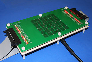
A sensor array is a group of sensors, usually deployed in a certain geometry pattern, used for collecting and processing electromagnetic or acoustic signals. The advantage of using a sensor array over using a single sensor lies in the fact that an array adds new dimensions to the observation, helping to estimate more parameters and improve the estimation performance. For example an array of radio antenna elements used for beamforming can increase antenna gain in the direction of the signal while decreasing the gain in other directions, i.e., increasing signal-to-noise ratio (SNR) by amplifying the signal coherently. Another example of sensor array application is to estimate the direction of arrival of impinging electromagnetic waves. The related processing method is called array signal processing. A third examples includes chemical sensor arrays, which utilize multiple chemical sensors for fingerprint detection in complex mixtures or sensing environments. Application examples of array signal processing include radar/sonar, wireless communications, seismology, machine condition monitoring, astronomical observations fault diagnosis, etc.

<span class="mw-page-title-main">Horn antenna</span> Funnel-shaped waveguide radio device

A horn antenna or microwave horn is an antenna that consists of a flaring metal waveguide shaped like a horn to direct radio waves in a beam. Horns are widely used as antennas at UHF and microwave frequencies, above 300 MHz. They are used as feed antennas for larger antenna structures such as parabolic antennas, as standard calibration antennas to measure the gain of other antennas, and as directive antennas for such devices as radar guns, automatic door openers, and microwave radiometers. Their advantages are moderate directivity, broad bandwidth, low losses, and simple construction and adjustment.

Beamforming or spatial filtering is a signal processing technique used in sensor arrays for directional signal transmission or reception. This is achieved by combining elements in an antenna array in such a way that signals at particular angles experience constructive interference while others experience destructive interference. Beamforming can be used at both the transmitting and receiving ends in order to achieve spatial selectivity. The improvement compared with omnidirectional reception/transmission is known as the directivity of the array.

<span class="mw-page-title-main">Directivity</span> Measure of how much of an antennas signal is transmitted in one direction

In electromagnetics, directivity is a parameter of an antenna or optical system which measures the degree to which the radiation emitted is concentrated in a single direction. It is the ratio of the radiation intensity in a given direction from the antenna to the radiation intensity averaged over all directions. Therefore, the directivity of a hypothetical isotropic radiator is 1, or 0 dBi.

<span class="mw-page-title-main">Radio-frequency microelectromechanical system</span>

A radio-frequency microelectromechanical system is a microelectromechanical system with electronic components comprising moving sub-millimeter-sized parts that provide radio-frequency (RF) functionality. RF functionality can be implemented using a variety of RF technologies. Besides RF MEMS technology, III-V compound semiconductor, ferrite, ferroelectric, silicon-based semiconductor, and vacuum tube technology are available to the RF designer. Each of the RF technologies offers a distinct trade-off between cost, frequency, gain, large-scale integration, lifetime, linearity, noise figure, packaging, power handling, power consumption, reliability, ruggedness, size, supply voltage, switching time and weight.

Radar engineering details are technical details pertaining to the components of a radar and their ability to detect the return energy from moving scatterers — determining an object's position or obstruction in the environment. This includes field of view in terms of solid angle and maximum unambiguous range and velocity, as well as angular, range and velocity resolution. Radar sensors are classified by application, architecture, radar mode, platform, and propagation window.

Wi-Fi positioning system is a geolocation system that uses the characteristics of nearby Wi‑Fi access point to discover where a device is located.

<span class="mw-page-title-main">Metamaterial antenna</span>

Metamaterial antennas are a class of antennas which use metamaterials to increase performance of miniaturized antenna systems. Their purpose, as with any electromagnetic antenna, is to launch energy into free space. However, this class of antenna incorporates metamaterials, which are materials engineered with novel, often microscopic, structures to produce unusual physical properties. Antenna designs incorporating metamaterials can step-up the antenna's radiated power.

Leaky-wave antenna (LWA) belong to the more general class of traveling wave antenna, that use a traveling wave on a guiding structure as the main radiating mechanism. Traveling-wave antenna fall into two general categories, slow-wave antennas and fast-wave antennas, which are usually referred to as leaky-wave antennas.

<span class="mw-page-title-main">Antenna array</span> Set of multiple antennas which work together

An antenna array is a set of multiple connected antennas which work together as a single antenna, to transmit or receive radio waves. The individual antennas are usually connected to a single receiver or transmitter by feedlines that feed the power to the elements in a specific phase relationship. The radio waves radiated by each individual antenna combine and superpose, adding together to enhance the power radiated in desired directions, and cancelling to reduce the power radiated in other directions. Similarly, when used for receiving, the separate radio frequency currents from the individual antennas combine in the receiver with the correct phase relationship to enhance signals received from the desired directions and cancel signals from undesired directions. More sophisticated array antennas may have multiple transmitter or receiver modules, each connected to a separate antenna element or group of elements.

<span class="mw-page-title-main">Two-ray ground-reflection model</span>

The two-rays ground-reflection model is a multipath radio propagation model which predicts the path losses between a transmitting antenna and a receiving antenna when they are in line of sight (LOS). Generally, the two antenna each have different height. The received signal having two components, the LOS component and the reflection component formed predominantly by a single ground reflected wave.

<span class="mw-page-title-main">Reconfigurable antenna</span> Antenna capable of modifying its frequency and radiation properties dynamically

A reconfigurable antenna is an antenna capable of modifying its frequency and radiation properties dynamically, in a controlled and reversible manner. In order to provide a dynamic response, reconfigurable antennas integrate an inner mechanism that enable the intentional redistribution of the RF currents over the antenna surface and produce reversible modifications of its properties. Reconfigurable antennas differ from smart antennas because the reconfiguration mechanism lies inside the antenna, rather than in an external beamforming network. The reconfiguration capability of reconfigurable antennas is used to maximize the antenna performance in a changing scenario or to satisfy changing operating requirements.

<span class="mw-page-title-main">Frequency selective surface</span> Optical filter

A frequency-selective surface (FSS) is any thin, repetitive surface designed to reflect, transmit or absorb electromagnetic fields based on the frequency of the field. In this sense, an FSS is a type of optical filter or metal-mesh optical filters in which the filtering is accomplished by virtue of the regular, periodic pattern on the surface of the FSS. Though not explicitly mentioned in the name, FSS's also have properties which vary with incidence angle and polarization as well - these are unavoidable consequences of the way in which FSS's are constructed. Frequency-selective surfaces have been most commonly used in the radio frequency region of the electromagnetic spectrum and find use in applications as diverse as the aforementioned microwave oven, antenna radomes and modern metamaterials. Sometimes frequency selective surfaces are referred to simply as periodic surfaces and are a 2-dimensional analog of the new periodic volumes known as photonic crystals.

The active reflection coefficient (ARC) is the reflection coefficient for a single antenna element in an array antenna, in the presence of mutual coupling. The active reflection coefficient is a function of frequency in addition to the excitation of the neighboring cells. In computational electromagnetics, the active reflection coefficient is usually determined from unit cell analysis in the frequency domain, where the phase shift over the unit cell is applied as a boundary condition. It has been suggested that the name "scan reflection coefficient" is more appropriate than "active reflection coefficient", however the latter remains the most commonly used name.

A Butler matrix is a beamforming network used to feed a phased array of antenna elements. Its purpose is to control the direction of a beam, or beams, of radio transmission. It consists of an matrix with hybrid couplers and fixed-value phase shifters at the junctions. The device has input ports to which power is applied, and output ports to which antenna elements are connected. The Butler matrix feeds power to the elements with a progressive phase difference between elements such that the beam of radio transmission is in the desired direction. The beam direction is controlled by switching power to the desired beam port. More than one beam, or even all of them can be activated simultaneously.

<span class="mw-page-title-main">Reflectarray antenna</span> Beam focusing, typically horn-fed planar array of unit cells

A reflectarray antenna consists of an array of unit cells, illuminated by a feeding antenna. The feeding antenna is usually a horn. The unit cells are usually backed by a ground plane, and the incident wave reflects off them towards the direction of the beam, but each cell adds a different phase delay to the reflected signal. A phase distribution of concentric rings is applied to focus the wavefronts from the feeding antenna into a plane wave . A progressive phase shift can be applied to the unit cells to steer the beam direction. It is common to offset the feeding antenna to prevent blockage of the beam. In this case, the phase distribution on the reflectarray surface needs to be altered. A reflectarray focuses a beam in a similar way to a parabolic reflector (dish), but with a much thinner form factor.

<span class="mw-page-title-main">Grating lobes</span>

For discrete aperture antennas in which the element spacing is greater than a half wavelength, a spatial aliasing effect allows plane waves incident to the array from visible angles other than the desired direction to be coherently added, causing grating lobes. Grating lobes are undesirable and identical to the main lobe. The perceived difference seen in the grating lobes is because of the radiation pattern of non-isotropic antenna elements, which effects main and grating lobes differently. For isotropic antenna elements, the main and grating lobes are identical.

References

  1. 1 2 3 4 5 L. Di Palma, A. Clemente, L. Dussopt, R. Sauleau, P. Potier, and P. Pouliguen, "Circularly-Polarized Reconfigurable Transmitarray in Ka-Band with Beam Scanning and Polarization Switching Capabilities," IEEE Transactions on Antennas and Propagation, vol. 65, no. 2, pp. 529–540, 2017.
  2. S. Datthanasombat, A. Prata Jr, L. R. Amaro, J. A. Harrell, S. Spitz and J. Perret, "Layered lens antenna," IEEE Antennas and Propagation Society International Symposium, Boston, USA, pp. 777-780, July 2001.
  3. B. Rahmati and H. R. Hassani, "High-efficient wideband slot transmitarray antenna," IEEE Transactions on Antennas and Propagation, vol. 63, no. 11, pp.5149–5155, 2015.
  4. 1 2 3 4 5 A. H. Abdelrahman, F. Yang, A.Z. Elsherbeni, and P. Nayeri, "Analysis and Design of Transmitarray Antennas", Morgan Claypool, Synthesis Lectures on Antennas, January 2017, Vol. 6, No. 1, 1st ed., San Rafael, CA, USA, pp. 7-12, 39-47, 2017.
  5. F. Diaby, A. Clemente, L. Di Palma, L. Dussopt, K. Pham, E. Fourn, and R. Sauleau, "Linearly-polarized electronically reconfigurable transmitarray antenna with 2-bit phase resolution in Ka-band," in 2017 19th International Conference on Electromagnetics in Advanced Applications (ICEAA), 2017, pp. 1295–1298.
  6. 1 2 T. A. Hill, "Millimetre Wave Lens and Transmitarray Antennas for Scan Loss Mitigation", PhD thesis, University of Surrey, UK, 2020.
  7. 1 2 G. Liu, H. J. Wang, J. S. Jiang, F. Xue, and M. Yi, "A High-Efficiency Transmitarray Antenna Using Double Split Ring Slot Elements," IEEE Antennas and Wireless Propagation Letters, vol. 14, pp. 1415–1418, 2015.
  8. A. Moknache, L. Dussopt, J. Saïly, A. Lamminen, M. Kaunisto, J. Aurinsalo, T. Bateman, and J. Francey, "A switched-beam linearly-polarized transmitarray antenna for V-band backhaul applications," in 2016 10th European Conference on Antennas and Propagation (EuCAP), 2016.
  9. H. Kaouach, L. Dussopt, J. Lanteri, T. Koleck, and R. Sauleau, "Wideband low loss linear and circular polarization transmit-arrays in V-Band," IEEE Transactions on Antennas and Propagation, vol. 59, no. 7, pp. 2513–2523, 2011.
  10. S. L. Liu, X. Q. Lin, Z. Q. Yang, Y. J. Chen, and J. W. Yu, "W-Band Low-Profile Transmitarray Antenna Using Different Types of FSS Units," IEEE Transactions on Antennas and Propagation, vol. 66, no. 9, pp. 4613–4619, Sept. 2018.
  11. Z. W. Miao, Z. C. Hao, G. Q. Luo, L. Gao, J. Wang, X. Wang, and W. Hong, "140 GHz High-Gain LTCC-Integrated Transmit-Array Antenna Using a Wideband SIW Aperture-Coupling Phase Delay Structure," IEEE Transactions on Antennas and Propagation, vol. 66, no. 1, pp. 182–190, Jan. 2018.
  12. J. Y. Lau, "Reconfigurable Transmitarray antennas," Ph.D. dissertation, University of Toronto, Canada, 2012.
  13. J. Y. Lau and S. V. Hum, "Reconfigurable transmitarray design approaches for beamforming applications," IEEE Transactions on Antennas and Propagation,vol. 60, no. 12, pp. 5679–5689, 2012.
  14. 1 2 L. Di Palma, "Antennes Réseaux Transmetteurs Reconfigurables aux Fréquences Millimétriques," Ph.D. dissertation, Université de Rennes 1, France, 2015.
  15. M. N. Bin Zawawi, "New Antenna for Millimetre Wave Radar," Ph.D. dissertation, Université Nice Sophia Antipolis, France, 2015.
  16. O. Yurduseven, D. L. Marks, J. N. Gollub, and D. R. Smith, "Design and Analysis of a Reconfigurable Holographic Metasurface Aperture for Dynamic Focusing in the Fresnel Zone," IEEE Access, vol. 5, pp. 15055–15065, 2017.
  17. O. Yurduseven, D. L. Marks, T. Fromenteze, and D. R. Smith, "Dynamically reconfigurable holographic metasurface aperture for a Mills-Cross monochromatic microwave camera," Optics Express, vol. 26, no. 5, pp. 5281–5291, Mar. 2018.
  18. P. Y. Feng, S. W. Qu, and S. Yang, "Phased Transmitarray Antennas for 1D Beam Scanning," IEEE Antennas and Wireless Propagation Letters, vol. 18, no. 2, pp. 358–362, Feb. 2019.
  19. A. Abbaspour-Tamijani, K. Sarabandi, and G. M. Rebeiz, "A millimetre-wave bandpass filter-lens array," IET Microwaves, Antennas Propagation, vol. 1, no. 2, pp. 388–395, Apr. 2007.
  20. A. Abbaspour-Tamijani, L. Zhang, and H. Pan, "Enhancing the directivity of phased array antennas using lens-arrays," Prog. Electromagn. Res., vol. 29, pp. 1–64, 2013.
  21. I. Uchendu and J. Kelly, "Survey of Beam Steering Techniques Available for Millimeter Wave Applications," Progress In Electromagnetics Research B, vol. 68, pp. 35–54, 2016.
  22. M. R. M. Hashemi, S.-H. Yang, T. Wang, N. Seplveda, and M. Jarrahi, "Electronically-controlled beam-steering through vanadium dioxide metasurfaces," Scientific Reports, vol. 6, May 2016, Article No. 35439.
  23. G. Perez-Palomino, "Contribution to the Analysis and Design of Reflectarray Antennas for Reconfigurable Beam Applications above 100 GHz using Liquid Crystal Technology," Ph.D. dissertation, Universidad Politécnica de Madrid, Spain, 2015.
  24. 1 2 S. Bildik, S. Dieter, C. Fritzsch, W. Menzel, and R. Jakoby, "Reconfigurable folded reflectarray antenna based upon liquid crystal technology," IEEE Transactions on Antennas and Propagation, vol. 63, no. 1, pp. 122–132, 2015.
  25. G. Perez-Palomino, J. Encinar, M. Barba, and E. Carrasco, "Design and evaluation of multi-resonant unit cells based on liquid crystals for reconfigurable reflectarrays," IET Microwaves, Antennas & Propagation, vol. 6, no. 3, pp. 348–354, 2012.
  26. G. Perez-Palomino, M. Barba, J. A. Encinar, R. Cahill, R. Dickie, P. Baine, and M. Bain, "Design and Demonstration of an Electronically Scanned Reflectarray Antenna at 100 GHz Using Multiresonant Cells Based on Liquid Crystals," IEEE Transactions on Antennas and Propagation, vol. 63, no. 8, pp. 3722–3727, 2015.
  27. M. Maasch, B. G. P. Evaristo, M. Mueh, and C. Damm, "Artificial gradient-index lens based on single unit cell layer fishnet metamaterial for phase correction of a horn antenna," in 2017 IEEE MTT-S International Microwave Symposium (IMS), June 2017, pp. 402–404.
  28. M. Maasch, M. Roig, C. Damm, and R. Jakoby, "Voltage-tunable artificial gradient-index lens based on a liquid crystal loaded fishnet metamaterial," IEEE Antennas and Wireless Propagation Letters, vol. 13, pp. 1581–1584, 2014.
  29. F. Diaby, A. Clemente, and L. Dussopt, "Design of a 3-Facet Linearly-Polarized Transmitarray Antenna at Ka-band," in 2018 IEEE Antennas and Propagation Society International Symposium (AP-S/URSI), 2018, pp. 2135–2136.
  30. D. M. Pozar, S. D. Targonski, and H. D. Syrigos, "Design of millimeter wave microstrip reflectarrays," IEEE Transactions on Antennas and Propagation, vol. 45, no. 2, pp. 287–296, 1997.
  31. A. H. Abdelrahman, P. Nayeri, A. Z. Elsherbeni, and F. Yang, "Analysis and design of wideband transmitarray antennas with different unit-cell phase ranges," in 2014 IEEE Antennas and Propagation Society International Symposium (APS/URSI), 2014, pp. 1266–1267.
  32. D. Ferreira, R. F. Caldeirinha, I. Cuinas, and T. R. Fernandes, "Square Loop and Slot Frequency Selective Surfaces Study for Equivalent Circuit Model Optimization," IEEE Transactions on Antennas and Propagation, vol. 63, no. 9, pp. 3947–3955, 2015.
  33. I. Munina, P. Turalchuk, А. Verevkin, V. Kirillov, D. Zelenchuk, A. Shitvov, "A Study of C-Band 1-Bit Reconfigurable Dual-Polarized Transmitarray," in 2019 13th European Conference on Antennas and Propagation (EuCAP), Krakow, Poland, April 2019.
  34. A. Clemente, L. Dussopt, R. Sauleau, P. Potier, and P. Pouliguen, "1-Bit Reconfigurable Unit Cell Based on PIN Diodes for Transmit-Array Applications in X-Band," IEEE Transactions on Antennas and Propagation, vol. 60, no. 5, pp. 2260–2269, May 2012.
  35. B. Schoenlinner, "Compact Wide Scan-Angle Antennas for Automotive Applications and RF MEMS Switchable Frequency-Selective Surfaces," Ph.D. disserta tion, University of Michigan, USA, 2004.
  36. 1 2 3 4 5 6 T. A. Hill, J. R. Kelly, M. Khalily, T. W. C. Brown, "Conformal Transmitarray for Scan Loss Mitigation with Thinned Reconfiguration," in 2019 13th European Conference on Antennas and Propagation (EuCAP), Krakow, Poland, April 2019.
  37. A. H. Abdelrahman, F. Yang, A. Z. Elsherbeni, and A. Khidre, "Transmitarray antenna design using slot-type element," in 2013 IEEE Antennas and Propagation Society International Symposium (AP-S/URSI), 2013, pp. 1356–1357.
  38. S. A. Matos, E. B. Lima, J. R. Costa, C. A. Fernandes, and N. J. Fonseca, "Generic formulation for transmit-array dual-band unit-cell design," in 2017 11th European Conference on Antennas and Propagation (EuCAP), 2017, pp. 2791–2794.
  39. J. R. Reis, N. Copner, A. Hammoudeh, Z. M. E. Al-Daher, R. F. Caldeirinha, T. R. Fernandes, and R. Gomes, "FSS-Inspired Transmitarray for Two Dimensional Antenna Beamsteering," IEEE Transactions on Antennas and Propagation, vol. 64, no. 6, pp. 2197–2206, 2016.
  40. H. Li, D. Ye, F. Shen, B. Zhang, Y. Sun, W. Zhu, C. Li, and L. Ran, "Reconfigurable diffractive antenna based on switchable electrically induced transparency," IEEE Transactions on Microwave Theory and Techniques, vol. 63, no. 3, pp. 925–936, 2015.
  41. MA4GP907 GaAs Flip Chip PIN Diode, MACOM, 2018 (accessed 20 August 2019). [Online]. Available: www.macom.com/products/product-detail/MA4GP907.
  42. K. Chang, I. Bahl, and V. Nair, RF and Microwave Circuit and Component Design for Wireless Systems, 1st ed. New York, USA: John Wiley & Sons, Inc., 2002.
  43. B. Orazbayev, M. Beruete, V. Pacheco-Peña, G. Crespo, J. Teniente, and M. Navarro-Cía, "Soret fishnet metalens antenna," Scientific Reports, vol. 5, May 2015, Article No. 9988.
  44. C. Pfeiffer and A. Grbic, "Millimeter-wave transmitarrays for wavefront and polarization control," IEEE Transactions on Microwave Theory and Techniques, vol. 61, no. 12, pp. 4407–4417, Dec. 2013.
  45. S.-W. Qu and H. Yi, "Low-cost two-layer terahertz transmitarray," in 2017 International Applied Computational Electromagnetics Society Symposium (ACES), Aug. 2017, pp. 1–2.
  46. F. F. Manzillo, A. Clemente, B. Blampey, G. Pares, A. Siligaris, and J. L. G. Jímenez, "Transmitarray Antenna with Integrated Frequency Multiplier for High speed D-band Communications in Low-Cost PCB Technology," in 2019 13th European Conference on Antennas and Propagation (EuCAP), 2019.
  47. F. F. Manzillo, A. Clemente, and J. L. Gonzalez-Jimenez, "High-gain D-band Transmitarrays in Standard PCB Technology for Beyond-5G Communications," IEEE Transactions on Antennas and Propagation, vol. 68, no. 1, pp. 587–592, 2020.
  48. F. F. Manzillo, J. L. Gonzalez-Jimenez, A. Clemente, A. Siligaris, B. Blampey, and C. Dehos, "Low-cost, High-Gain Antenna Module Integrating a CMOS Frequency Multiplier Driver for Communications at D-band," in 2019 IEEE Radio Frequency Integrated Circuits Symposium, 2019, pp. 19–22.