Easting and northing coordinates are commonly measured in metres from the axes of some horizontal datum. However, other units (e.g., survey feet) are also used. The coordinates are most commonly associated with the Universal Transverse Mercator coordinate system (UTM), which has unique zones that cover the Earth to provide detailed referencing.
Notation and conventions
Locations can be found using easting/northing (or x, y) pairs. The pair is usually represented conventionally with easting first, northing second.
For example, the peak of Mount Assiniboine (at 50°52′10″N115°39′03″W / 50.86944°N 115.65083°W / 50.86944; -115.65083) in UTM Zone 11 is represented by 11U 0594934 5636174. Subset conventions can also be used, such as a truncated grid reference,[1] where the general location is already known to participants and may be assumed. Because the (leading) most significant digits specify the part of the world and the (trailing) least significant digits provide a precision that is not needed in most circumstances, they may be redundant for trekking use. This permits users to shorten the example coordinates to 949-361 by concealing 11U 05nnn34 56nnn74.
Usually associated with a map projection is a natural origin, e.g., at which the ellipsoid and flat map surfaces coincide.[2] To ensure that the northing and easting coordinates on a map are not negative, map projections may set up a false origin, specified in terms of false northing and false easting values, that offset the true origin. Otherwise, negative northing and easting values indicate a position south and west of the origin, respectively.
The grid lines on Ordnance Survey maps divide the UK into one-kilometre squares, east of an imaginary zero point in the Atlantic Ocean, west of Cornwall. The grid lines point to a Grid North, varying slightly from True North. This variation is zero on the central meridian (north-south line) of the map, which is at two degrees West of the Prime Meridian, and greatest at the map edges. The difference between grid north and true north is very small and can be ignored for most navigation purposes. The difference exists because the correspondence between a flat map and the round Earth is necessarily imperfect.
At the South Pole, grid north conventionally points northwards along the Prime Meridian.[4] Since the meridians converge at the poles, true east and west directions change rapidly in a condition similar to gimbal lock. Grid north solves this problem.
To establish the position of a geographic location on a map, a map projection is used to convert geodetic coordinates to plane coordinates on a map; it projects the datum ellipsoidal coordinates and height onto a flat surface of a map. The datum, along with a map projection applied to a grid of reference locations, establishes a grid system for plotting locations. Common map projections in current use include the Universal Transverse Mercator (UTM), the Military Grid Reference System (MGRS), the United States National Grid (USNG), the Global Area Reference System (GARS) and the World Geographic Reference System (GEOREF).[5] Coordinates on a map are usually in terms northing N and easting E offsets relative to a specified origin.
Map projection formulas depend on the geometry of the projection as well as parameters dependent on the particular location at which the map is projected. The set of parameters can vary based on the type of project and the conventions chosen for the projection. For the transverse Mercator projection used in UTM, the parameters associated are the latitude and longitude of the natural origin, the false northing and false easting, and an overall scale factor.[2] Given the parameters associated with particular location or grin, the projection formulas for the transverse Mercator are a complex mix of algebraic and trigonometric functions.[2]:45-54
Types
Grid systems vary, but the most common is a square grid with grid lines intersecting each other at right angles and numbered sequentially from the origin at the bottom left of the map. The grid numbers on the east-west (horizontal) axis are called Eastings, and the grid numbers on the north-south (vertical) axis are called Northings.
Numerical grid references consist of an even number of digits. Eastings are written before Northings. Thus in a 6 digit grid reference 123456, the Easting component is 123 and the Northing component is 456, i.e. if the smallest unit is 100 metres, it refers to a point 12.3km east and 45.6km north from the origin.
Grids may be arbitrary, or can be based on specific distances, for example some maps use a one-kilometre square grid spacing.
A grid reference locates a unique square region on the map. The precision of location varies, for example a simple town plan view may use a simple alphanumeric grid system with single letters for Eastings and single numbers for Northings. A grid reference in this system, such as 'H3', locates a particular square rather than a single point.
Points can be located by grid references on maps that use a standard system for Eastings and Northings, such as the Universal Transverse Mercator used worldwide, or the Ordnance Survey National Grid used by Ordnance Survey in the UK. These points can then be located by someone else using grid references, even if using maps of a different scale.
In the Universal Transverse Mercator (UTM) system, grid reference is given by three numbers: zone, easting and northing. In the UTM system, the Earth is divided into 60 zones. Northing values are given by the metres north, or south (in the southern hemisphere) of the equator. Easting values are established as the distance from the central meridian of a zone. The central meridian is arbitrarily set at 500,000 metres, to avoid negative numbers. A position 100 kilometres west of a central meridian would have an easting of 400,000 metres. Due to its popularity, and worldwide cover, the UTM system is used worldwide by NATO as well as many countries, including Australia and the USA.[6]
In the United Kingdom, a proprietary grid system is used. In Ordnance Survey maps, each Easting and Northing grid line is given a two-digit code, based on the British national grid reference system with an origin point just off the southwest coast of the United Kingdom. The area is divided into 100km squares, each of which is denoted by a two-letter code. Within each 100km square, a numerical grid reference is used. Since the Eastings and Northings are one kilometre apart, a combination of a Northing and an Easting will give a four-digit grid reference describing a one-kilometre square on the ground. The convention is the grid reference numbers call out the lower-left corner of the desired square. In the example map above, the town Little Plumpton lies in the square 6901, even though the writing which labels the town is in 6802 and 6902, most of the buildings (the orange boxed symbols) are in square 6901.
The more digits added to a grid reference, the more precise the reference becomes. To locate a specific building in Little Plumpton, a further two digits are added to the four-digit reference to create a six-digit reference. The extra two digits describe a position within the 1-kilometre square. Imagine (or draw or superimpose a Romer) a further 10x10 grid within the current grid square. Any of the 100 squares in the superimposed 10×10 grid can be accurately described using a digit from 0 to 9 (with 0 0 being the bottom left square and 9 9 being the top right square).
For the church in Little Plumpton, this gives the digits 6 and 7 (6 on the left to right axis (Eastings) and 7 on the bottom to top axis (Northings). These are added to the four-figure grid reference after the two digits describing the same coordinate axis, and thus our six-figure grid reference for the church becomes 696017. This reference describes a 100-metre by 100-metre square, and not a single point, but this precision is usually sufficient for navigation purposes. The symbols on the map are not precise in any case, for example the church in the example above would be approximately 100x200 metres if the symbol was to scale, so in fact, the middle of the black square represents the map position of the real church, independently of the actual size of the church.
Grid references comprising larger numbers for greater precision could be determined using large-scale maps and an accurate Romer. This might be used in surveying but is not generally used for land navigating for walkers or cyclists, etc. The growing availability and decreasing cost of handheld GPS receivers enables determination of accurate grid references without needing a map, but it is important to know how many digits the GPS displays to avoid reading off just the first six digits. A GPS unit commonly gives a ten-digit grid reference, based on two groups of five numbers for the Easting and Northing values. Each successive increase in precision (from 6 digit to 8 digit to 10 digit) pinpoints the location more precisely by a factor of 10. Since, in the UK at least, a 6-figure grid reference identifies a square of 100-metre sides, an 8-figure reference would identify a 10-metre square, and a 10-digit reference a 1-metre square. In order to give a standard 6-figure grid reference from a 10-figure GPS readout, the 4th, 5th, 9th and 10th digits must be omitted, so it is important not to read just the first 6 digits.
Amateur radio operators use the Maidenhead Locator System to succinctly describe their geographic coordinates. It alternates pairs of letters and pairs of numbers to encode latitude and longitude to increasing specificity. The grid runs from A to R in both longitude and latitude starting from (-180°, -90°), and these are then divided into single-digit values in both directions. The location EM, for example, covers 20° by 10° and runs from the central United States through its southeast, and EM48 is 2° by 1° in size and lies in eastern Missouri, including St. Louis.
The Universal Transverse Mercator (UTM) and Universal Polar Stereographic (UPS) coordinate systems both use a metric-based Cartesian grid laid out on a conformally projected surface to locate positions on the surface of the Earth. The UTM system is not a single map projection but a series of sixty, each covering 6-degree bands of longitude. The UPS system is used for the polar regions, which are not covered by the UTM system.
In cartography, a map projection is a way to flatten a globe's surface into a plane in order to make a map. This requires a systematic transformation of the latitudes and longitudes of locations from the surface of the globe into locations on a plane.
The Ordnance Survey National Grid reference system is a system of geographic grid references used in Great Britain, distinct from latitude and longitude.
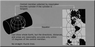
The transverse Mercator map projection is an adaptation of the standard Mercator projection. The transverse version is widely used in national and international mapping systems around the world, including the Universal Transverse Mercator. When paired with a suitable geodetic datum, the transverse Mercator delivers high accuracy in zones less than a few degrees in east-west extent.
The Irish grid reference system is a system of geographic grid references used for paper mapping in Ireland. The Irish grid partially overlaps the British grid, and uses a similar co-ordinate system but with a meridian more suited to its westerly location.
The Military Grid Reference System (MGRS) is the geocoordinate standard used by NATO militaries for locating points on Earth. The MGRS is derived from the Universal Transverse Mercator (UTM) grid system and the Universal Polar Stereographic (UPS) grid system, but uses a different labeling convention. The MGRS is used as geocode for the entire Earth.
The Swiss coordinate system is a geographic coordinate system used in Switzerland and Liechtenstein for maps and surveying by the Swiss Federal Office of Topography (Swisstopo).
The Universal Transverse Mercator (UTM) is a map projection system for assigning coordinates to locations on the surface of the Earth. Like the traditional method of latitude and longitude, it is a horizontal position representation, which means it ignores altitude and treats the earth as a perfect ellipsoid. However, it differs from global latitude/longitude in that it divides earth into 60 zones and projects each to the plane as a basis for its coordinates. Specifying a location means specifying the zone and the x, y coordinate in that plane. The projection from spheroid to a UTM zone is some parameterization of the transverse Mercator projection. The parameters vary by nation or region or mapping system.
The universal polar stereographic (UPS) coordinate system is used in conjunction with the universal transverse Mercator (UTM) coordinate system to locate positions on the surface of the earth. Like the UTM coordinate system, the UPS coordinate system uses a metric-based cartesian grid laid out on a conformally projected surface. UPS covers the Earth's polar regions, specifically the areas north of 84°N and south of 80°S, which are not covered by the UTM grids, plus an additional 30 minutes of latitude extending into UTM grid to provide some overlap between the two systems.
A spatial reference system (SRS) or coordinate reference system (CRS) is a framework used to precisely measure locations on the surface of the Earth as coordinates. It is thus the application of the abstract mathematics of coordinate systems and analytic geometry to geographic space. A particular SRS specification comprises a choice of Earth ellipsoid, horizontal datum, map projection, origin point, and unit of measure. Thousands of coordinate systems have been specified for use around the world or in specific regions and for various purposes, necessitating transformations between different SRS.
The United States National Grid (USNG) is a multi-purpose location system of grid references used in the United States. It provides a nationally consistent "language of location", optimized for local applications, in a compact, user friendly format. It is similar in design to the national grid reference systems used in other countries. The USNG was adopted as a national standard by the Federal Geographic Data Committee (FGDC) of the US Government in 2001.
The State Plane Coordinate System (SPCS) is a set of 124 geographic zones or coordinate systems designed for specific regions of the United States. Each state contains one or more state plane zones, the boundaries of which usually follow county lines. There are 110 zones in the contiguous US, with 10 more in Alaska, 5 in Hawaii, and one for Puerto Rico and US Virgin Islands. The system is widely used for geographic data by state and local governments. Its popularity is due to at least two factors. First, it uses a simple Cartesian coordinate system to specify locations rather than a more complex spherical coordinate system. By using the Cartesian coordinate system's simple XY coordinates, "plane surveying" methods can be used, speeding up and simplifying calculations. Second, the system is highly accurate within each zone. Outside a specific state plane zone accuracy rapidly declines, thus the system is not useful for regional or national mapping.
Jordan Transverse Mercator (JTM) is a grid system created by the Royal Jordan Geographic Center (RJGC). This system is based on 6° belts with a Central Meridian of 37° East and a Scale Factor at Origin (mo) = 0.9998. The JTM is based on the Hayford ellipsoid adopted by the IUGG in 1924. No transformation parameters are presently offered by the government. However, Prof. Stephen H. Savage of Arizona State University provides the following parameters for the projection:
Irish Transverse Mercator (ITM) is the geographic coordinate system for Ireland. It was implemented jointly by the Ordnance Survey Ireland (OSi) and the Ordnance Survey of Northern Ireland (OSNI) in 2001. The name is derived from the Transverse Mercator projection it uses and the fact that it is optimised for the island of Ireland.
Israeli Transverse Mercator (ITM), also known as the New Israel Grid is the new geographic coordinate system for Israel. The name is derived from the transverse Mercator projection it uses and the fact that it is optimized for Israel. ITM has replaced the old coordinate system Israeli Cassini Soldner (ICS), also known as the Old Israel Grid (OIG). It became the official grid for Israel in 1998.
Israeli Cassini Soldner (ICS), commonly known as the Old Israeli Grid is the old geographic coordinate system for Israel. The name is derived from the Cassini Soldner projection it uses and the fact that it is optimized for Israel. ICS has been mostly replaced by the new coordinate system Israeli Transverse Mercator (ITM), also known as the New Israeli Grid (NIG), but still referenced by older books and navigation software.
The Hellenic Geodetic Reference System 1987 or HGRS87 is a geodetic system commonly used in Greece (SRID=2100). The system specifies a local geodetic datum and a projection system. In some documents it is called Greek Geodetic Reference System 1987 or GGRS87.
The article Transverse Mercator projection restricts itself to general features of the projection. This article describes in detail one of the (two) implementations developed by Louis Krüger in 1912; that expressed as a power series in the longitude difference from the central meridian. These series were recalculated by Lee in 1946, by Redfearn in 1948, and by Thomas in 1952. They are often referred to as the Redfearn series, or the Thomas series. This implementation is of great importance since it is widely used in the U.S. State Plane Coordinate System, in national and also international mapping systems, including the Universal Transverse Mercator coordinate system (UTM). They are also incorporated into the Geotrans coordinate converter made available by the United States National Geospatial-Intelligence Agency. When paired with a suitable geodetic datum, the series deliver high accuracy in zones less than a few degrees in east-west extent.
The Cassini Grid was a grid coordinate system used on British military maps during the first half of the twentieth century, particularly during World War II. The referencing consists of square grids drawn on a Cassini projection. For a period after the war, the maps were also used by the general public. The system has been superseded by the Ordnance Survey National Grid.
The Gauss–Boaga projection is a map projection used in Italy that uses a Hayford ellipsoid.
The Palestine grid was the geographic coordinate system used by the Survey Department of Palestine.
This page is based on this Wikipedia article Text is available under the CC BY-SA 4.0 license; additional terms may apply. Images, videos and audio are available under their respective licenses.