Tool used on a machine to accurately align the head with the work prior to machining
This article may be confusing or unclear to readers. In particular, differentiate the types (edge/center) of tool. Define kickoff and collet. Further explain the context and usage of the tool - is it moved across the work or pressed down against it? What does an operator observe or manipulate? How does a collet help accuracy? What constitutes a proper setup or an improper one? Explain why digital is erroneous. Are the repeatabilities dependent on the quality of the tool, operator, both, or neither? How is a center finder different than a school pencil?. Please help clarify the article. There might be a discussion about this on the talk page.(May 2017) ( Learn how and when to remove this message )
Set of wigglers
A wiggler, also known as a wobbler, edge-finder, center-finder or laser-centering-device, is a tool used with a machine like a mill, to accurately align the machine head with the work prior to machining.
An edge finder is a rotating tool, meaning the machine spindle must be turning for the tool to work. On one end of a cylindrical shank, a second cylinder is attached by a spring running through the center of both cylinders. The second cylinder rotates with the first. The axes of the two cylinders are always parallel, but the mating faces are able to slide against each other. Thus the second cylinder can rotate about a different, but always parallel axis to the first.
As the second cylinder approaches the edge to be located, it is pushed into alignment with the first. When the horizontal distance from the workpiece to the axis of the shank is exactly equal to the radius of the second cylinder, the second cylinder turns perfectly coaxially with the shank. Even a very small displacement in the direction of the workpiece cause the second cylinder to "kick off" and displace dramatically along the workpiece edge.
On the other end, a cone shape is also spring-loaded and is used to locate the center of a previously drilled hole. This style of edge finder is considered to be the most accurate, and its accuracy can be further improved through the use of a collet. In proper setups, a repeatability of 0.0002in (0.0051mm) or better can be obtained.
Electronic edge finder
Electronic edge finder
An electronic edge finder, is an instrument that can locate edges of work pieces and also height offsets. It works in a non-rotating spindle, which is a great advantage over its mechanical counterparts. It is battery-operated and works by lighting up its internal LED (usually red) when the electrical circuit formed by the instrument, the workpiece and the machine is closed. The light is thus illuminated when the edge finder is touching the workpiece and is visible through openings in the case. A repeatability of 0.001in (0.025mm) can be obtained.
Center finder
Center finder
A center finder is a tool used to align the machining center to a precision location on a work piece. Often these locations might be marked using a layout method (coating the surface with layout stain and scribing a precise location with the intersection of the two lines identifying the position to be machined, etc. Sometimes a magnifying glass is used to assist in marking the location. One drawback of this method is that it is only as accurate as the lines that are drawn on the part.
In contrast to the edge finder, in the mechanical versions, the tip is not spring-loaded, and it works with the spindle stopped. In laser versions, an 'X' of light is often projected from the machining center onto the work piece and the work piece location is adjusted to align with the intersection of these lines. In contrast to centering devices, the center finder cannot directly find the center of a work piece, thus requires additional calculation, measurement and/or layout method to align to.
Centering device
Centering of a shaft with a laser centering device
A centering device is a tool used to accurately adjust and align the center plane or axis of a work piece or work piece feature to the machining center. In contrast to the edge finder, it most often requires no calculation, measurements or layout method markings to allow this alignment. Mechanical versions may work with the spindle stopped. Laser centering devices can be used to cast patterns of light which, depending on angle of the laser, can achieve a high degree of precision.
A lathe is a machine tool that rotates a workpiece about an axis of rotation to perform various operations such as cutting, sanding, knurling, drilling, deformation, facing, threading and turning, with tools that are applied to the workpiece to create an object with symmetry about that axis.
Metalworking is the process of shaping and reshaping metals in order to create useful objects, parts, assemblies, and large scale structures. As a term, it covers a wide and diverse range of processes, skills, and tools for producing objects on every scale: from huge ships, buildings, and bridges, down to precise engine parts and delicate jewelry.
Machining is a manufacturing process where a desired shape or part is created using the controlled removal of material, most often metal, from a larger piece of raw material by cutting. Machining is a form of subtractive manufacturing, which utilizes machine tools, in contrast to additive manufacturing, which uses controlled addition of material.
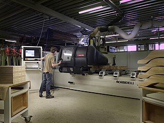
In machining, numerical control, also called computer numerical control (CNC), is the automated control of tools by means of a computer. It is used to operate tools such as drills, lathes, mills, grinders, routers and 3D printers. CNC transforms a piece of material into a specified shape by following coded programmed instructions and without a manual operator directly controlling the machining operation.
Drilling is a cutting process where a drill bit is spun to cut a hole of circular cross-section in solid materials. The drill bit is usually a rotary cutting tool, often multi-point. The bit is pressed against the work-piece and rotated at rates from hundreds to thousands of revolutions per minute. This forces the cutting edge against the work-piece, cutting off chips (swarf) from the hole as it is drilled.
A reamer is a type of rotary cutting tool used in metalworking. Precision reamers are designed to enlarge the size of a previously formed hole by a small amount but with a high degree of accuracy to leave smooth sides. There are also non-precision reamers which are used for more basic enlargement of holes or for removing burrs. The process of enlarging the hole is called reaming. There are many different types of reamer and they may be designed for use as a hand tool or in a machine tool, such as a milling machine or drill press.
Woodturning is the craft of using a wood lathe with hand-held tools to cut a shape that is symmetrical around the axis of rotation. Like the potter's wheel, the wood lathe is a mechanism that can generate a variety of forms. The operator is known as a turner, and the skills needed to use the tools were traditionally known as turnery. In pre-industrial England, these skills were sufficiently difficult to be known as "the mysteries of the turners' guild." The skills to use the tools by hand, without a fixed point of contact with the wood, distinguish woodturning and the wood lathe from the machinist's lathe, or metal-working lathe.
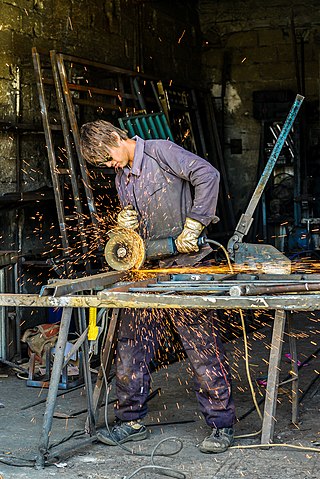
A grinding machine, often shortened to grinder, is any of various power tools or machine tools used for grinding. It is a type of material removal using an abrasive wheel as the cutting tool. Each grain of abrasive on the wheel's surface cuts a small chip from the workpiece via shear deformation.
A collet is a segmented sleeve, band or collar. One of the two radial surfaces of a collet is usually tapered and the other is cylindrical. The term collet commonly refers to a type of chuck that uses collets to hold either a workpiece or a tool, but collets have other mechanical applications.
A chuck is a specialized type of clamp used to hold an object with radial symmetry, especially a cylinder. In a drill, a mill and a transmission, a chuck holds the rotating tool; in a lathe, it holds the rotating workpiece.
A punch press is a type of machine press used to cut holes in material. It can be small and manually operated and hold one simple die set, or be very large, CNC operated, with a multi-station turret and hold a much larger and complex die set.
Turning is a machining process in which a cutting tool, typically a non-rotary tool bit, describes a helix toolpath by moving more or less linearly while the workpiece rotates.
A lathe center, often shortened to center, is a tool that has been ground to a point to accurately position a workpiece on an axis. They usually have an included angle of 60°, but in heavy machining situations an angle of 75° is used.
In machining, a metal lathe or metalworking lathe is a large class of lathes designed for precisely machining relatively hard materials. They were originally designed to machine metals; however, with the advent of plastics and other materials, and with their inherent versatility, they are used in a wide range of applications, and a broad range of materials. In machining jargon, where the larger context is already understood, they are usually simply called lathes, or else referred to by more-specific subtype names. These rigid machine tools remove material from a rotating workpiece via the movements of various cutting tools, such as tool bits and drill bits. Metal lathes can vary greatly, but the most common design is known as the universal lathe or parallel lathe.
In machining, boring is the process of enlarging a hole that has already been drilled by means of a single-point cutting tool, such as in boring a gun barrel or an engine cylinder. Boring is used to achieve greater accuracy of the diameter of a hole, and can be used to cut a tapered hole. Boring can be viewed as the internal-diameter counterpart to turning, which cuts external diameters.
Grinding is a type of abrasive machining process which uses a grinding wheel as cutting tool.
In manufacturing, threading is the process of creating a screw thread. More screw threads are produced each year than any other machine element. There are many methods of generating threads, including subtractive methods ; deformative or transformative methods ; additive methods ; or combinations thereof.
Surface grinding is done on flat surfaces to produce a smooth finish.
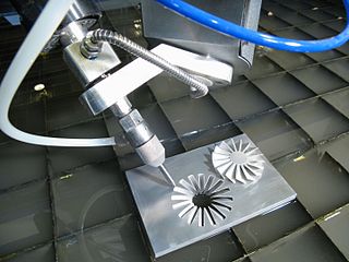
Multiaxis machining is a manufacturing process that involves tools that move in 4 or more directions and are used to manufacture parts out of metal or other materials by milling away excess material, by water jet cutting or by laser cutting. This type of machining was originally performed mechanically on large complex machines. These machines operated on 4, 5, 6, and even 12 axes which were controlled individually via levers that rested on cam plates. The cam plates offered the ability to control the tooling device, the table in which the part is secured, as well as rotating the tooling or part within the machine. Due to the machines size and complexity it took extensive amounts of time to set them up for production. Once computer numerically controlled machining was introduced it provided a faster, more efficient method for machining complex parts.
Milling is the process of machining using rotary cutters to remove material by advancing a cutter into a workpiece. This may be done by varying directions on one or several axes, cutter head speed, and pressure. Milling covers a wide variety of different operations and machines, on scales from small individual parts to large, heavy-duty gang milling operations. It is one of the most commonly used processes for machining custom parts to precise tolerances.
This page is based on this Wikipedia article Text is available under the CC BY-SA 4.0 license; additional terms may apply. Images, videos and audio are available under their respective licenses.