Asynchronous connection-oriented logical transport
Last updated
The Bluetooth Asynchronous Connection-oriented logical transport (ACL) is one of two types of logical transport defined in the Bluetooth Core Specification, either BR/EDR ACL or LE ACL. BR/EDR ACL is the ACL logical transport variant used with Bluetooth Basic Rate/Enhanced Data Rate (BR/EDR, also known as Bluetooth Classic) whilst LE ACL is the ACL logical transport variant used with Bluetooth Low Energy (LE).
The ACL transports are part of the Bluetooth data transport architecture.
Note that all definitions of Bluetooth terminology, protocols and procedures including ACL are defined in the Bluetooth Core Specification[1] which is published by the standards development organisation, the Bluetooth Special Interest Group (Bluetooth SIG).
The Bluetooth Data Transport Architecture
The architecture section of the Bluetooth Core Specification defines a number of concepts which collectively constitute the Bluetooth data transport architecture. Key amongst these concepts are the Physical Channel, Physical Link, Logical Link and Logical Transport. Certain combinations are intended for use in different application types which have particular requirements regarding issues such as topology, timing, reliability and radio channel use.
The LE ACL logical transport is used with either an LE-C logical link, which carries control data or an LE-U logical link which is for user data. It is based on an LE Active Physical Link and the LE Piconet Physical Channel. See Figure 1.
Figure 1 - The LE-ACL logical transport within the Bluetooth data transport architecture
The BR/EDR ACL logical transport is used with either an ACL-C logical link for control data or an ACL-U logical link for user data and it is based on a BR/EDR Active Physical Link and either the BR/EDR Basic Piconet Physical Channel or the BR/EDR Adapted Piconet Physical Channel. See Figure 2.
Figure 2 - The BR/EDR ACL logical transport within the Bluetooth data transport architecture
Both ACL variants are designed to provide reliable, bi-directional, point to point communication.
LE ACL
Overview
A Bluetooth LE Central device may establish a connection with an advertising Peripheral device by responding to a received connectable advertising packet with a PDU that requests a connection. A number of parameters are specified in the request. Amongst these parameters are connection interval, supervision timeout, peripheral latency and channel map.
The connection interval parameter defines how often in milliseconds, the radio can be used for servicing this connection. Whenever the connection interval timer expires, a connection event is said to begin and at this point, the Central device in the connection may transmit a link layer packet. At the start of each connection event, the radio channel to be used is selected using a procedure known as adaptive frequency hopping.
The Peripheral device, possessing the same connection parameters as the Central device knows when to expect transmitted packets from the Central device and over which channel. If the value of the Peripheral Latency connection parameter is zero, the Peripheral must reply to the Central device 150 microseconds (+/- 2µs) after receiving the last bit of the Central’s packet. Central and Peripheral may then proceed to exchange a further implementation-defined number of packets during the remainder of the connection event. Note that the Peripheral’s behavior may be modified by a non-zero Peripheral Latency parameter value.
Figure 3 shows a basic exchange of packets, during two connection events with C>P indicating packet transmission by the Central device and P>C by the Peripheral.
Figure 3 - Basic packet exchange over a Bluetooth LE-ACL connection (C denotes the Central device, P denotes the Peripheral device)
Packets exchanged over an LE ACL connection contain either LL Data PDUs or LL Control PDUs which are associated with Link Layer control procedures. If either device has no data to transmit and transmission of a packet is required, it must send an empty LL Data PDU.
The Supervision Timeout parameter specifies the maximum time which may elapse between two Link Layer data packets having been received before the link is considered to have been lost.
The Peripheral is not required to listen for packets from the Central device during every connection event. The Peripheral Latency parameter defines the number of consecutive connection events during which the Peripheral does not have to be listening. This gives the Peripheral the opportunity to save power.
Figure 4 shows the behavior of the Peripheral with Peripheral Latency = 1 and therefore listening during alternate connection events only. The Central may transmit during those events where the Peripheral is not listening, but such packets will not be received and therefore will not be acknowledged, ending the connection event.
Figure 4 - A Bluetooth LE-ACL connection with Peripheral Latency=1 (C denotes the Central device, P denotes the Peripheral device)
Acknowledgement and Flow Control
Link layer data packets contain three important fields which contribute to communication being reliable. These fields are called the Sequence Number (SN), Next Expected Sequence Number (NESN), and the More Data field. All three of these fields are single bit fields and their use provides a system of acknowledgements and a method for checking for the correct ordering of received packets.
Communication starts with the Central device (Device A in Figure 5) sending a link layer data packet with SN and NESN both set to zero. From this point on, at each packet exchange that takes place, if all is well, the value of the SN field as set by Device A, will alternate between zero and one. The other device (Device B) always knows therefore, what the SN value of the next packet to be received should be and checks for this.
If Device B receives a packet from Device A with the expected SN value, it responds with a link layer data packet that has NESN set to the logical value NOT(SN). So for example, if the received SN value was 1 then NESN in the response will be 0.
When Device A receives a response from Device B with NESN set to the value that Device A intends to use for SN in its next packet, Device A takes this to be an acknowledgement from Device B, confirming that it received the last transmitted packet correctly. Figure 5 shows this.
Figure 5 - A successful exchange of Bluetooth packets at the link layer
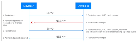
If Device B receives a packet with the wrong SN value, it assumes that the packet is the retransmission of the previous packet received, acknowledges it but does not pass it up the stack for further processing.
If Device A receives an unexpected NESN value in a reply from Device B or does not receive a reply at all, it resends the packet with the same SN value used originally. Different controller implementations are free to implement varying algorithms regarding how many times to resend before concluding communication to have failed. See Figure 6.
Figure 6 - Bluetooth link layer retransmissions
Each packet contains a CRC field and encrypted packets also contain an MIC field. On receiving a packet, the link layer checks the CRC and if present, the MIC. If either check fails, the packet is not acknowledged, and this generally results in the originator of the packet resending it. See Figure 7.
Figure 7 - Behaviour of the Bluetooth link layer when a CRC failure occurs
Channel Use
LE-ACL employs a spread spectrum scheme known as adaptive frequency hopping. At the start of each connection event, frequency hopping occurs, with one of the 37 general purpose Bluetooth LE radio channels being selected from the set of available channels using a channel selection algorithm. Each device in the connection will then switch to the selected channel and over time and a series of connection events, communication will take place using a frequently changing series of different channels, distributed across the 2.4 GHz band, thereby significantly reducing the probability of collisions occurring.
A channel map is maintained by the Central device and may also be maintained by the Peripheral device. This is a table of data which indicates which channels are available for use and which are not. Implementations mark channels as used or unused according to how well each channel is performing in terms or errors and evidence of interference. Unused channels are not selected by the channel selection algorithm. In this way, adaptive frequency hopping dynamically adjusts the channels used for active communication according to the prevailing RF conditions in the environment.
Link Control
A number of control procedures relating to LE ACL connections are defined. A selection of examples appears in Table 1.
Table 1 - Example Link Layer control procedures
Control Procedure
Description
Connection Update
Allows either the Central or Peripheral device to request changes to the connection parameters connection interval, peripheral latency and supervision timeout.
Channel Map Update
Allows the Central device to transfer its latest channel map data to the connected Peripheral.
Encryption
Allows either Central or Peripheral to enable the encryption of packets.
Feature Exchange
Allows Central or Peripheral to initiate an exchange of the Link Layer features each device supports, encoded as a bitmap field.
Periodic Advertising Sync Transfer
Allows either Central or Peripheral to transfer periodic advertising synchronization information relating to a periodic advertising train that has been discovered to the other device over an LE ACL connection.
CIS Creation Procedure
Allows a Central device to create a Connected Isochronous Stream (CIS) with the Peripheral.
Power Control Request
Allows one peer to request that the other peer adjust its transmit power level.
Channel Classification Reporting
Allows a Peripheral to report channel classification data to the connected Central.
Subrated Connections
Subrated connections are LE ACL connections which have additional properties assigned to them and behave differently in some ways. The additional properties are called the subrate factor, subrate base event, and continuation number.
The subrated connection properties provide a mechanism for indicating that only a specific subset of connection events is to be actively used by the connected devices, with the radio not being used in other connection events. A subrated connection can therefore have a short ACL connection interval which allows low latency at the application layer but still exhibit a low duty cycle.
Figure 8 illustrates the basic concepts relating to subrated connections.
Figure 8 - Bluetooth LE subrated connection basic concept
Here we can see that only one in every five connection events is used by either Central or Peripheral. The other four are skipped and so there is no radio activity during those connection events. This ratio of used to skipped connection events is determined by the subrate factor parameter and in this example it is set to 5.
Subrated connections have a number of special Link Layer control procedures defined for use with them. For example, there is a procedure for updating subrated connection parameters which works differently to the general Connection Update procedure. Critically, changes to subrated connection parameters can be applied almost instantaneously whereas general connection parameter changes can take a significant amount of time to take effect. The advantage of subrated connections therefore is that persistent connections which exhibit a low duty cycle and consume little power can be established and can be switched to a high duty cycle, high bandwidth connection with no delay that any user could notice. This capability has particular applicability in some LE Audio scenarios such as those involving hearing aids and smartphones.
The Bluetooth Core Specification Version 5.3 Feature Enhancements paper has a substantial chapter dedicated to the subject of subrated connections and is recommended as a source of further information.
BR/EDR ACL
Overview
Communication using a BR/EDR ACL logical transport is similar to the LE ACL variant and provides an asynchronous point-to- point communication mechanism for exchanging data between a Central device and a Peripheral.
When a BR/EDR device joins a piconet, a default ACL logical transport automatically created. Other logical transport types (e.g., SCO - BR/EDR synchronous connection-oriented) between the same pair of devices are dependent upon the default ACL and if it is removed then the other logical transports are also removed.
BR/EDR ACL connections make use of time slots defined by the underlying physical channel. Central and Peripheral devices alternately transmit and receive during a subset of these time slots, allocated by the implementation. Synchronous logical transports are given priority such that BR/EDR connections use only those time slots that have not been reserved for synchronous communication.
Six packet types for defined for Bluetooth Basic Rate (BR) and are named DM1, DH1, DM3, DH3, DM5 and DH5. Bluetooth Enhanced Data Rate (EDR) defines a further six packet types named 2-DH1, 3-DH1, 2-DH3, 3-DH3, 2-DH5 and 3-DH5. A packet type AUX1 is defined for use in testing.
A BR/EDR ACL connection is established by a Peripheral device paging a Central device. The Central device performs page scanning.
Acknowledgments and Ordering
1-bit header fields ARQN and SEQN are used to allow positive or negative acknowledgements to be made and to verify that the order of packets received is as it should be.
Flow Control
The RX buffer associated with BR/EDR ACL connections may become full. The header field FLOW is used to provide a simple flow control mechanism with values in responses indicating STOP or GO.
Channel Use
Adaptive frequency hopping (a responsibility of the underlying physical channel) is in effect when using the BR/EDR ACL logical transport, with a channel selected at each reception or transmission event. 79 channels are defined for use with Bluetooth BR/EDR and there are a number of different possible hopping patterns defined.
Link Control
The Link Manager Protocol (LMP) defines a series of PDU types which allow the control of and negotiation over details of the BR/EDR ACL logical transport to be carried out. LMP PDUs are sent over an ACL-C logical link.
This page is based on this Wikipedia article Text is available under the CC BY-SA 4.0 license; additional terms may apply. Images, videos and audio are available under their respective licenses.