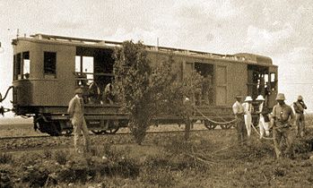
South African gas-electric locomotive

Last updated

South African gas-electric locomotive
Gas-electric locomotive.jpg
Experimental gas-electric locomotive, c. 1923
Type and origin
Power typeGas-electric
Designer South African Railways
(C. Lawson)
BuilderSouth African Railways
ModelGE1
Build date1923
Total produced1
Specifications
Configuration:
   AAR 1A-A1
   UIC (1A)(A1)
  Commonwealth1A-A1
Gauge 3 ft 6 in (1,067 mm) Cape gauge
Minimum curve 3%
Length:
  Over beams40 ft (12.2 m)
Axle load 7 long tons (7.1 t; 7.8 short tons) average
Loco weight28 long tons (28.4 t; 31.4 short tons)
Fuel typeSmokebox char
Prime mover Holt (Caterpillar tractor)
RPM range750-800
  RPM low idle750
  Maximum RPM800
Engine typePetrol
Traction motors Two Siemens 50 hp (37 kW)
Couplers Johnston link-and-pin
Performance figures
Maximum speed25 mph (40 km/h)
Power output85 hp (63 kW)
Career
Operators South African Railways
Number in class1
NumbersGE1
First run1923

The South African Railways gas-electric locomotive of 1923 was an experimental gas-electric locomotive. The fuel, suction gas, was generated on-board the locomotive from coal.

Contents

In 1923, the South African Railways experimented with gas-electric motive power and constructed a single experimental producer gas-electric locomotive. The locomotive remained in service for several years and was followed by another, built by the General Electric Company, which was not successful and never entered line service after undergoing experimental trials. The gas-electric concept was eventually superseded by diesel-electric traction. [1] [2] [3]

Branch line non-profitability

The non-profitability of many branch line operations had been a problem for the South African Railways (SAR) from the outset. The question of non-paying branch lines was raised by Sir William Hoy, South African Railways and Harbours General Manager, in a paper read at the Imperial Motor Transport Conference in London in 1913. He drew attention to the fact that, in isolated districts with vast agricultural and mineral capabilities in many parts of the Union of South Africa, development was hampered by the lack of means of transportation. [1]

In an attempt to reduce the cost of using steam locomotives on infrequently used and non-profitable branch lines, other forms of motive power were considered in the early 1920s. Diesel and diesel-electric locomotives were still in their infancy and were therefore not yet an attractive proposition, while the cost of electrification of such branch lines would be prohibitive. The first alternative form of traction to enter service was the Dutton road-rail tractor system in 1923. [1] [2]

During October 1922, Hoy encouraged further experiments to determine the practicability of the use of suction gas (also known as producer gas) as fuel for an alternative form of motive power, suitable for use on branch lines. Mr. C. Lawson, Superintendent Mechanical of the SAR, was tasked with the experiment. [1] [3]

Suction gas principle

Combustion gases, rich in carbon monoxide and known variously as water gas, producer gas and mond gas, are generated by passing air and steam through some kind of red-hot burning carbonaceous fuel, usually coal. The gas generator consists of a combustion portion, where the fuel is initially burned to generate the required steam. The steam is then blown through this same burning fuel, taking air with it, and the producer gas is then liberated as a by-product of this combustion. Ordinarily, burning produces carbon dioxide, but by forcing steam through the burn a certain amount of incomplete combustion is caused which produces carbon monoxide. [3]

Depending on the vessel used, the gas created may be under a slight pressure caused by the velocity of the steam and an expansion chamber is used to reduce this pressure. Experimenting established that the suction created by a petrol engine running on the gas actually increased the generation of the producer gas by drawing more steam and air through the burn. This could possibly make the expansion chamber superfluous. Producer gas generated by this method became known as suction gas. With a suction gas engine, the amount of gas produced is therefore partially dependent on the speed and throttle setting of the engine using it. [3]

Development

Lawson's experimental locomotive was based on the same principle as contemporary Swedish diesel-electric locomotives, except that the diesel engine prime mover would be replaced by a petrol engine running on carbon monoxide producer gas. As with a diesel-electric locomotive, an electric generator and traction motor combination would be used to transfer the engine's power to the wheels. [3]

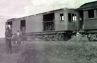
The locomotive was constructed on an old 40 feet (12.2 metres) bogie truck underframe. The producer gas generator was constructed from the smokebox section of a scrapped 6th Class locomotive's boiler. Smokebox char was used as fuel and the gas was passed from the gas generator through suitable wet scrubbers to remove tar to two Tilling-Stevens petrol engines. The engines came from Whippet tanks and were obtained from the Defence Department. A gas expansion chamber was constructed from an old chimney. The two engines drove shunt wound dynamos, obtained from General Electric, to power the traction motors which were two tramway motors obtained from De Beers in Kimberley. Since the gas was generated by the suction from the two internal combustion engines, the vehicle became known as a suction gas locomotive. [1] [2] [3]

The locomotive ran in three forms. During the experimental stage, it was run from Germiston to Johannesburg station as a flat truck with all the components assembled on top and occupying about half of the deck space, but uncovered, to be viewed by the members of the Railway Board. [1] [2] [3]

During the testing stage, an enclosed body was added. During a 167-mile long (269-kilometre) test run to Volksrust, various adjustments were made to the water circulating arrangements. This improved the power output to the extent that the tram traction motors were unable to stand the continuous current which was generated, and they were replaced by two 50 horsepower (37 kilowatts) Siemens traction motors supplied by General Electric. These, in turn, required more current than the Whippet engines could generate and they were replaced by a 120 horsepower (89 kilowatts) Holt engine from a Caterpillar tractor, supplied by Messrs Fraser and Chalmers of Bulawayo in Southern Rhodesia. [3]

The gas generator was never altered in principle from the first experiment and the expansion chamber was kept as it was, but the original wet scrubber was replaced with a dry scrubber early during development. Control of electrical current was by two tramway series-parallel controllers and resistors to ensure a range of speeds. The current generated with the engine at its normal working of 750 revolutions per minute was 140 amperes and 500 volts. 600 volts could be obtained by speeding up the engine, but this could place a too heavy load on the generator. [3]

Service

In its final guise, a small third-class compartment for twenty passengers was added on the unused deck space at the rear. The 28 long tons (28.4 metric tons; 31.4 short tons) locomotive, numbered GE1, was capable of negotiating a 3% curve at 6 miles per hour (10 kilometres per hour) and could attain a top speed of 25 miles per hour (40 kilometres per hour) on level track. [1] [2] [3]

The Gas-electric locomotive was finally placed in service on the Winter's Rush branch line from Kimberley, where it often hauled a passenger coach. It remained in service on that line for several years. [2]

Termination

In June 1923, Colonel F.R. Collins DSO, the SAR Chief Mechanical Engineer, approved plans for a 200 horsepower (150 kilowatts) suction gas locomotive, but it never materialised. In 1925, a new 280 horsepower (210 kilowatts) suction gas locomotive was purchased instead. It was designed to SAR specifications by Mr. Harry Ricardo of Ricardo Brothers of Shoreham and built by the General Electric Company in England. At the time, it was claimed to be the largest of its type in the world, but it never emerged from the trial stages. It was found that the variable demand on the gas generator precluded a regular supply of gas of the required quality. The gas-electric locomotive was eventually superseded by the diesel-electric locomotive, which proved to be a far more convenient and much less cumbersome machine to operate over long distances. [1] [2] [3]

No more suction gas locomotives were acquired. The experimental gas-electric locomotive's frame, bogies and traction motors were used c. 1935 to construct a unique electric motor coach, numbered 9181 and classified as U-34-M. It was placed in service hauling a trailer coach between Mason's Mill and Pietermaritzburg, where it was known as the Mason’s Mill Shuttle. Since the earlier Cape motor-coaches still worked under 1,500 V DC at the time, EMU no. 9181 was the first SAR motor-coach to operate under 3 kV DC catenary. [1] [4]

Illustration

The main picture shows engine no. GE1 in service on the Winter's Rush branch line, while the following photographs all show it during development and testing, c. 1923.

Related Research Articles

<span class="mw-page-title-main">Locomotive</span> Self-propelled railway vehicle

A locomotive is a rail transport vehicle that provides the motive power for a train. If a locomotive is capable of carrying a payload, it is usually rather referred to as a multiple unit, motor coach, railcar or power car; the use of these self-propelled vehicles is increasingly common for passenger trains, but rare for freight trains.

<span class="mw-page-title-main">Diesel locomotive</span> Locomotive powered by a diesel engine

A diesel locomotive is a type of railway locomotive in which the power source is a diesel engine. Several types of diesel locomotives have been developed, differing mainly in the means by which mechanical power is conveyed to the driving wheels. The most common are diesel–electric locomotives and diesel–hydraulic.

<span class="mw-page-title-main">Stationary engine</span>

A stationary engine is an engine whose framework does not move. They are used to drive immobile equipment, such as pumps, generators, mills or factory machinery, or cable cars. The term usually refers to large immobile reciprocating engines, principally stationary steam engines and, to some extent, stationary internal combustion engines. Other large immobile power sources, such as steam turbines, gas turbines, and large electric motors, are categorized separately.

<span class="mw-page-title-main">British Rail 18000</span>

British Rail 18000 was a prototype mainline gas turbine–electric locomotive built for British Railways in 1949 by Brown, Boveri & Cie. An earlier gas-turbine locomotive, 18100, had been ordered from Metropolitan-Vickers by the Great Western Railway but construction was delayed due to World War II; a second, 18000, was thus ordered from Switzerland in 1946. It spent its working life on the Western Region of British Railways, operating express passenger services from Paddington station, London.

The following lists events that happened during 1923 in South Africa.

<span class="mw-page-title-main">Gas turbine locomotive</span> Type of railway locomotive

A gas turbine locomotive is a type of railway locomotive in which the prime mover is a gas turbine. Several types of gas turbine locomotive have been developed, differing mainly in the means by which mechanical power is conveyed to the driving wheels (drivers). A gas turbine train typically consists of two power cars, and one or more intermediate passenger cars.
<span class="mw-page-title-main">British Rail 18100</span>

British Rail 18100 was a prototype main line gas turbine–electric locomotive built for British Railways in 1951 by Metropolitan-Vickers, Manchester. It had, however, been ordered by the Great Western Railway in the 1940s, but construction was delayed due to World War II. It spent its working life on the Western Region of British Railways, operating express passenger services from Paddington station, London.

A hybrid train is a locomotive, railcar or train that uses an onboard rechargeable energy storage system (RESS), placed between the power source and the traction transmission system connected to the wheels. Since most diesel locomotives are diesel-electric, they have all the components of a series hybrid transmission except the storage battery, making this a relatively simple prospect.

A steam diesel hybrid locomotive is a railway locomotive with a piston engine which could run on either steam from a boiler or diesel fuel. Examples were built in the United Kingdom, Soviet Union and Italy but the relatively high cost of fuel oil, or failure to resolve problems caused by technical complexity, meant that the designs were not pursued.

<span class="mw-page-title-main">Union Pacific GTELs</span> Fleet of gas turbine–electric locomotives

The Union Pacific GTELs were a series of gas turbine–electric locomotives built by Alco-GE and General Electric from 1952 to 1961 and operated by Union Pacific from 1952 to 1970.

<span class="mw-page-title-main">SBB-CFF-FFS Am 4/6 1101</span>

Am 4/6 1101 was the world's first gas turbine–electric locomotive. The locomotive was ordered by the Swiss Federal Railways (SBB-CFF-FFS) from the Swiss Locomotive and Machine Works (SLM) and Brown, Boveri & Cie (BBC) in 1939. The locomotive was delivered in 1941 and was in use on railroads in Switzerland, France and Germany until 1954.

<span class="mw-page-title-main">South African Class 26 4-8-4</span> 1981 design of steam locomotive

The South African Railways Class 26 4-8-4 of 1981, popularly known as the Red Devil, is a 4-8-4 steam locomotive which was rebuilt from a Class 25NC locomotive by mechanical engineer David Wardale from England while in the employ of the South African Railways. The rebuilding took place at the Salt River Works in Cape Town and was based on the principles developed by Argentinian mechanical engineer L.D. Porta.

<span class="mw-page-title-main">South African Class 61-000</span> Type of diesel-hydraulic locomotive

The South African Railways Class 61-000 of 1959 was a diesel-hydraulic locomotive.

<span class="mw-page-title-main">South African Class 2E</span> South African electric locomotive

The South African Railways Class 2E of 1937 was an electric locomotive.

The Heilmann locomotives were a series of three experimental steam–electric locomotives produced in the 1890s for the French Chemins de fer de l'Ouest. A prototype was built in 1894 and two larger locomotives were built in 1897. These locomotives used electric transmission, much like later-popular diesel–electric locomotives and various other self-powered locomotives.
<span class="mw-page-title-main">South African Class ES1</span> Class of 1 South African battery-electric locomotive

The South African Railways Class ES1 of 1924 was an electric locomotive.

<span class="mw-page-title-main">South African Class DS</span> South african locomotive

The South African Railways Class DS of 1939 was a diesel-electric locomotive.
<span class="mw-page-title-main">South African Class DS1</span> Class of 1 South African 0-6-0de locomotive

The South African Railways Class DS1 of 1939 was a diesel-electric locomotive.

<span class="mw-page-title-main">1Co+Co1</span>

Under the British and Imperial classification scheme of locomotive axle arrangements 1Co+Co1 is a classification code for a locomotive wheel arrangement of two eight-wheeled bogies with an articulated inter-bogie connection, each with three axles powered by a separate traction motor per axle and with the fourth non-powered axle in an integral leading pony truck to reduce the axle load. The similar 1Co-Co1 classification is in the same axle configuration, but without the inter-bogie connection.

An internal combustion locomotive is a type of railway locomotive that produces its pulling power using an internal combustion engine. These locomotives are fuelled by burning fossil fuels, most commonly oil or gasoline, to produce rotational power which is transmitted to the locomotive's driving wheels by various direct or indirect transmission mechanisms. The fuel is carried on the locomotive.

References

  1. 1 2 3 4 5 6 7 8 9 Espitalier, T.J.; Day, W.A.J. (1945). The Locomotive in South Africa - A Brief History of Railway Development. Chapter VII - South African Railways (Continued). South African Railways and Harbours Magazine, October 1945. pp. 782-783.
  2. 1 2 3 4 5 6 7 Paxton, Leith; Bourne, David (1985). Locomotives of the South African Railways (1st ed.). Cape Town: Struik. p. 118-119. ISBN   0869772112.
  3. 1 2 3 4 5 6 7 8 9 10 11 Heymans, Brig. H.B.; Parsley, Dr. G.M.J. (2000).The SAR Experimental Suction Gas-Electric Locomotive. Paper dated 28 September 2000.
  4. Soul of A Railway, System 6, Part 5: The New Main Line from Rossburgh to Pietermaritzburg compiled by Les Pivnic. Captions 96-97. (Accessed on 26 August 2017)