South African Class 6E1, Series 1

Last updated

South African Class 6E1, Series 1
SAR Class 6E1 Series 1 E1228.JPG
E1228 at Warrenton in August 2007
Type and origin
Power typeElectric
Designer Union Carriage & Wagon
BuilderUnion Carriage & Wagon
ModelUCW 6E1
Build date1969-1970
Total produced20
Specifications
Configuration:
   AAR B-B
   UIC Bo′Bo′
  Commonwealth Bo-Bo
Gauge 3 ft 6 in (1,067 mm) Cape gauge
Wheel diameter1,220 mm (48.03 in)
Wheelbase 11,279 mm (37 ft 116 in)
   Bogie 3,430 mm (11 ft 3 116 in)
Pivot centres7,849 mm (25 ft 9 in)
Panto shoes6,972 mm (22 ft 10 12 in)
Length:
  Over couplers15,494 mm (50 ft 10 in)
  Body14,631 mm (48 ft 0 in)
Width2,896 mm (9 ft 6 in)
Height:
  Pantograph4,089 mm (13 ft 5 in)
  Body height3,937 mm (12 ft 11 in)
Axle load 22,226 kg (49,000 lb)
Adhesive weight 88,904 kg (196,000 lb)
Loco weight88,904 kg (196,000 lb)
Electric system/s 3 kV DC catenary
Current pickup(s) Pantographs
Traction motors Four AEI-283AZ
  Rating 1 hour623 kW (835 hp)
  Continuous563 kW (755 hp)
Gear ratio18:67
Loco brake Air & Regenerative
Train brakes Air & Vacuum
Couplers AAR knuckle
Performance figures
Maximum speed113 km/h (70 mph)
Power output:
  1 hour2,492 kW (3,342 hp)
  Continuous2,252 kW (3,020 hp)
Tractive effort:
  Starting311 kN (70,000 lbf)
  1 hour221 kN (50,000 lbf)
  Continuous193 kN (43,000 lbf) @ 40 km/h (25 mph)
Career
Operators South African Railways
Spoornet
Transnet Freight Rail
Class Class 6E1
Number in class20
NumbersE1226-E1245
Delivered1969-1970
First run1969

The South African Railways Class 6E1, Series 1 of 1969 was an electric locomotive.

Contents

In 1969 and 1970, the South African Railways placed twenty Class 6E1, Series 1 electric locomotives with a Bo-Bo wheel arrangement in mainline service. Their limited number and the fact that they entered service before the Class 6E suggest that the Class 6E1, Series 1 units were obtained as demonstrators on redesigned bogies, before a decision was made on which of the two types would be perpetuated. [1] [2]

Manufacturer

The 3 kV DC Class 6E1, Series 1 electric locomotive was designed and built for the South African Railways (SAR) in 1969 and 1970 by Union Carriage & Wagon (UCW) in Nigel, Transvaal, with the electrical equipment being supplied by Associated Electrical Industries and English Electric. [3] [4]

Twenty units were delivered in 1969 and 1970, numbered in the range from E1226 to E1245. UCW did not allocate builder’s or works numbers to the locomotives it built for the SAR and used the SAR unit numbers for their record keeping. [1]

Characteristics

Orientation

These dual cab locomotives had a roof access ladder on one side only, just to the right of the cab access door. The roof access ladder end was marked as the no. 2 end. A corridor along the centre of the locomotive connected the cabs which were identical apart from the fact that the handbrake was located in cab 2. A pantograph hook stick was stowed in a tube mounted below the bottom edge of the locomotive body on the roof access ladder side. The units had one square and two rectangular access panels along the lower half of the body on the roof access ladder side, and only one square access panel on the opposite side. [1]

The Class 6E1, Series 1 was delivered in the new body shape with squared corners that had been introduced part-way through the construction of the Class 5E1, Series 5, and was equipped with double sealed-beam automobile headlamps. The body dimensions were the same as that of the Class 5E1, Series 5 and the most visually obvious external difference was the replacement of the three small vertically arranged grilles to the right of centre on each side of the Classes 5E and 5E1 with a larger double grille on each side of the Class 6E1. Since the traction struts on the new Class 6E1 bogie allowed room for only one footstep instead of the earlier three to be mounted on the bogie, a stirrup step was added, attached to the bodywork directly below the side door. [5]

Bogies

The twenty Series 1 locomotives were identical to the Class 6E in most respects including their AEI-283AZ traction motors, power output, tractive force and body dimensions. The only visually obvious distinguishing feature to tell the Class 6E1, Series 1 apart was its new design bogies with their distinctive traction struts and linkages. [1] [6]

Bogie frame and wheels Class 6E1 Bogie.jpg
Bogie frame and wheels

Together with the unit's electronic wheelslip detection system, these traction struts, mounted between the linkages on the bogies and the locomotive body and colloquially referred to as grasshopper legs, ensured the maximum transfer of power to the rails without causing wheel-slip by reducing the adhesion of the leading bogie and increasing that of the trailing bogie by as much as 15% upon starting off. This feature was controlled by electronic wheel-slip detection devices and an electric weight transfer relay which reduced the anchor current to the leading bogie by as much as 50A in notches 2 to 16. These grasshopper legs and linkages were to become a distinguishing feature on the bogies of most subsequent South African electric locomotive classes. [6]

The limited number of Class 6E1, Series 1 locomotives that were placed in service and the fact that they entered service a year before the Class 6E suggest that the Series 1 locomotives were obtained as demonstrators for these new bogies to be evaluated before a decision was made about their continued production. [2]

Series identifying features

The Class 6E1 was produced in eleven series over a period of nearly sixteen years with altogether 960 units placed in service, all built by UCW. This made the Class 6E1 the most numerous single locomotive class ever to have seen service in South Africa and serves as ample proof of a highly successful design. [1] [6]

Class 6E1, Series 1 bogie Class 6E1 E1232 bogie.jpg
Class 6E1, Series 1 bogie

While some Class 6E1 series are visually indistinguishable from their predecessors or successors, some externally visible changes did occur over the years. Like the Classes 5E, 5E1 and 6E, the Class 6E1, Series 1 units had their sandboxes mounted on the bogies while all the subsequent series Class 6E1s had their sandboxes mounted along the bottom edge of the locomotive body with the sandbox lids fitting into four cut-outs in the body on each side. [1] [6]

Operation

Startup

When there was no compressed air in the unit's system to raise a pantograph to start up, a pantograph hook stick was used to manually raise the pantograph. This started the high voltage motor which drove the auxiliary alternator to supply 110 V power to start the compressor and power other control circuits. Once there was enough main air pressure to keep the pantograph in the raised position, the pantograph hook stick could be removed. [7]

The unit was controlled via resistors over which the voltage was dropped in a configuration of series and parallel electrical circuits. The circuit breakers that switched these circuits worked under very high power and voltage and were therefore all pneumatically operated for insulation purposes. Compressed air was required to open or close the switch actions and air was also used for the weak-field Cam Switch that also switched under very high currents. [7]

Running

Upon starting off and in the low notches, the major part of the voltage was dropped over the banks of resistors and all four traction motors were in series. The blowers which accelerated the dissipation of heat in the resistor banks gave the Class 6E1 its very distinctive sound, a deep and loud whine when power was applied. [2] [7]

As the driver notched up, some of the resistor banks were cut out via the pneumatically-operated switches and the voltage increased across the traction motors. As the driver notched higher, more resistors were cut out and more power was developed by the traction motors. At around 22 to 28 kilometres per hour (14 to 17 miles per hour) the unit switched to a parallel combination where the two traction motors per bogie were in a series electrical circuit while the two bogies were in a parallel electrical circuit. Eventually, when all resistors were cut out, the unit was operating in full-field. [7]

When the traction motors were operated in full-field, be it in series or parallel mode, they were performing at maximum power for normal operation. To increase the speed at this point, if necessary, higher power output was required from the traction motors. The only way to increase power was to force a higher current flow. To accomplish this, the weak-field cam switch switched resistance in parallel with the field coils, which reduced the overall resistance of the field coils. This increased the magnetic flux and more power was generated by the traction motors, but only over short periods. [7]

Brakes

The unit itself used air brakes, but it was equipped to operate trains with air or vacuum brakes. The brake system would be set up for either air or vacuum train working by means of a turning switch on the driver's brake valve and by pre-setting the appropriate brake valves in the corridor.

Compressed air pipes Class 18E 18-089 compressed air pipes.jpg
Compressed air pipes

The Class 6E1 units were built with an air brake system that consisted of various valves connected to each other with pipes, commonly referred to as a "bicycle frame" brake system. The compressed air pipes ran under the unit's belly in a zig-zag pattern, going through bolster and other members to extend its length to allow the maximum amount of moisture to condense on the way to the reservoirs. As a result, it had multiple pipe connections. A weakness of the system was that, after an accident or even a hard coupling, these pipes tended to develop leaks at the joints which were extremely difficult to repair. [8]

While hauling a vacuum braked train, the unit's air brake system would be disabled and the train would be controlled by using the train brakes alone to slow down and stop. While hauling an air braked train, on the other hand, the unit's brakes would engage along with the train brakes. While working either type of train downgrade, the unit's regenerative braking system would also work in conjunction with the train brakes.

Unlike the Classes 5E and 5E1 whose air brakes could be applied independently on each bogie when the locomotive was stopped, the air brakes on both bogies would be applied together on the Classes 6E and 6E1. The handbrake or parking brake, located in cab 2, only operated on the unit's last axle, or no. 7 and 8 wheels.

Service

The Class 6E1 family saw service all over both 3 kV DC mainline and branch line networks. [3]

Cape Western network

The smaller network is the Cape Western mainline between Cape Town and Beaufort West, with the units based at the Bellville Depot in Cape Town. [3]

Northern network

The larger network covers portions of the Northern Cape, the Free State, Natal, Gauteng, North West and Mpumalanga, the main routes in this vast area being as follows: [3]

The electric locomotives allocated to depots within this network were largely pooled and could operate anywhere in the network as required by the Operating Department, but they returned to their home depots for maintenance every twenty-eight days. [3]

In 2011, the Class 6E1 began to be withdrawn from the Natal Corridor (NatCor) mainline between Johannesburg and Durban and replaced by rebuilt Class 18E locomotives. [3]

In KwaZulu-Natal, the coastal sections from Durban to Empangeni in the north and to Port Shepstone in the south were due to be dieselised at the end of October 2011, using EMD Classes 34 and 37-000 locomotives which were being displaced by the introduction of new Class 43-000 diesel-electric locomotives on the line from Mpumalanga via Swaziland to Richards Bay. [9]

In practice, however, electric locomotives were observed at Port Shepstone as late as 24 May 2012 while the diesel power on the South Coast line consisted predomiminantly of Class 37-000 locomotives. The overhead catenary equipment between Stanger and Empangeni and between Kelso and Port Shepstone was to be removed soon after the end of October 2011, but actual removal only took place in November 2013. By October 2014, the catenary masts, sans wiring, were still standing at Port Shepstone.

Liveries

The whole series was delivered in the SAR Gulf Red livery with signal red cowcatchers, yellow whiskers and with the number plates on the sides enclosed in three-stripe yellow wings. In the 1990s many of the Series 1 units began to be repainted in the Spoornet orange livery with a yellow and blue chevron pattern on the cowcatchers. By 2000 they were all repainted in this new livery. [10]

Illustration

Related Research Articles

MetroBlitz

MetroBlitz was an experimental high speed commuter train service between Pretoria station and Johannesburg Park Station via Germiston, operated by the South African Transport Services (SATS). It started service on 16 January 1984.

South African Class 1E

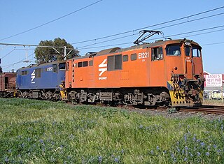
The South African Railways Class 1E of 1925 was an electric locomotive.

South African Class 5E1, Series 1

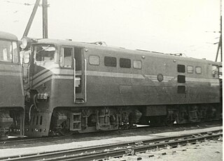
The South African Railways Class 5E1, Series 1 of 1959 was an electric locomotive.

South African Class 5E1, Series 3

The South African Railways Class 5E1, Series 3 of 1964 was an electric locomotive.

South African Class 6E

The South African Railways Class 6E of 1970 was an electric locomotive.

South African Class 6E1, Series 4

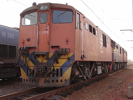
The South African Railways Class 6E1, Series 4 of 1973 was an electric locomotive.

South African Class 7E

The South African Railways Class 7E of 1978 is an electric locomotive.

South African Class 7E1

The South African Railways Class 7E1 of 1980 is an electric locomotive.

South African Class 7E2, Series 1

The South African Railways Class 7E2, Series 1 of 1982 is an electric locomotive.

South African Class 7E3, Series 2

The South African Railways Class 7E3, Series 2 of 1984 is an electric locomotive.

South African Class 9E, Series 1

The South African Railways Class 9E, Series 1 of 1978 is an electric locomotive.

South African Class 9E, Series 2

The South African Railways Class 9E, Series 2 of 1982 is an electric locomotive.

South African Class 10E

The South African Railways Class 10E of 1985 is an electric locomotive.

South African Class 10E1, Series 1

The South African Railways Class 10E1, Series 1 of 1987 is an electric locomotive.

South African Class 10E2

The South African Railways Class 10E2 of 1989 is an electric locomotive.

South African Class 12E

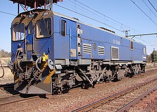
The South African Railways Class 12E of 1983 was an electric locomotive.

South African Class 16E

The Spoornet Class 16E of 1990 was a South African electric locomotive.

South African Class 17E

The Spoornet Class 17E of 1993 was a South African electric locomotive.

South African Class 18E, Series 1

The Spoornet Class 18E, Series 1 of 2000 is a South African electric locomotive.

South African Class 20E

The Transnet Freight Rail Class 20E of 2013 is a South African electric locomotive.

References

  1. 1 2 3 4 5 6 South African Railways Index and Diagrams Electric and Diesel Locomotives, 610mm and 1065mm Gauges, Ref LXD 14/1/100/20, 28 January 1975, as amended
  2. 1 2 3 Dulez, Jean A. (2012). Railways of Southern Africa 150 Years (Commemorating One Hundred and Fifty Years of Railways on the Sub-Continent – Complete Motive Power Classifications and Famous Trains – 1860–2011) (1st ed.). Garden View, Johannesburg, South Africa: Vidrail Productions. p. 297. ISBN   9 780620 512282.
  3. 1 2 3 4 5 6 Middleton, John N. (2002). Railways of Southern Africa Locomotive Guide - 2002 (as amended by Combined Amendment List 4, January 2009) (2nd, Dec 2002 ed.). Herts, England: Beyer-Garratt Publications. pp. 49–51.
  4. "UCW - Electric locomotives" (PDF). The UCW Partnership. Archived from the original (PDF) on 12 October 2007. Retrieved 30 September 2010.
  5. Soul of A Railway, System 7, Western Transvaal, based in Johannesburg, Part 20: Natalspruit to Vereeniging, Part 3. Caption 30. (Accessed on 29 April 2017)
  6. 1 2 3 4 Paxton, Leith; Bourne, David (1985). Locomotives of the South African Railways (1st ed.). Cape Town: Struik. pp. 128–129. ISBN   0869772112.
  7. 1 2 3 4 5 Operation - South African Classes 6E, 6E1, 16E, 17E and 18E
  8. Information obtained from Transnet engineers and drivers.
  9. Railways Africa, 18 Oct 2011: KwaZulu-Natal coastal region de-electrification
  10. Soul of A Railway, System 7, Western Transvaal, based in Johannesburg, Part 9. South-Eastwards as far as Volksrust (2nd part) by Les Pivnic. Caption 4. (Accessed on 11 April 2017)