Stirling cycle

Last updated

The Stirling cycle is a thermodynamic cycle that describes the general class of Stirling devices. This includes the original Stirling engine that was invented, developed and patented in 1816 by Robert Stirling with help from his brother, an engineer. [1]

Contents

The ideal Otto and Diesel cycles are not totally reversible because they involve heat transfer through a finite temperature difference during the irreversible isochoric/isobaric heat-addition and heat-rejection processes. The irreversibility renders the thermal efficiency of these cycles less than that of a Carnot engine operating within the same limits of temperature. Another cycle that features isothermal heat-addition and heat-rejection processes is the Stirling cycle, which is an altered version of the Carnot cycle in which the two isentropic processes featured in the Carnot cycle are replaced by two constant-volume regeneration processes.

The cycle is reversible, meaning that if supplied with mechanical power, it can function as a heat pump for heating or cooling, and even for cryogenic cooling. The cycle is defined as a closed regenerative cycle with a gaseous working fluid. "Closed cycle" means the working fluid is permanently contained within the thermodynamic system. This also categorizes the engine device as an external heat engine. "Regenerative" refers to the use of an internal heat exchanger called a regenerator which increases the device's thermal efficiency.

The cycle is the same as most other heat cycles in that there are four main processes: compression, heat addition, expansion, and heat removal. However, these processes are not discrete, but rather the transitions overlap.

The Stirling cycle is a highly advanced subject that has defied analysis by many experts for over 190 years. Highly advanced thermodynamics is required to describe the cycle. Professor Israel Urieli writes: "...the various 'ideal' cycles (such as the Schmidt cycle) are neither physically realizable nor representative of the Stirling cycle". [2]

The analytical problem of the regenerator (the central heat exchanger in the Stirling cycle) is judged by Jakob to rank "among the most difficult and involved that are encountered in engineering". [3] [4]

Idealized Stirling cycle thermodynamics

A pressure/volume graph of the idealized Stirling cycle. In real applications of the Stirling cycles (e.g. Stirling engines) this cycle is quasi-elliptical. Stirling cycle pV.svg
A pressure/volume graph of the idealized Stirling cycle. In real applications of the Stirling cycles (e.g. Stirling engines) this cycle is quasi-elliptical.

The idealized Stirling [5] cycle consists of four thermodynamic processes acting on the working fluid (See diagram to right):

  1. 1→2 Isothermal heat addition (expansion).
  2. 2→3 Isochoric heat removal (constant volume).
  3. 3→4 Isothermal heat removal (compression).
  4. 4→1 Isochoric heat addition (constant volume).

Piston motion variations

A model of a four-phase Stirling cycle Ideal-stirling-cycle.gif
A model of a four-phase Stirling cycle

Most thermodynamics textbooks describe a highly simplified form of Stirling cycle consisting of four processes. This is known as an "ideal Stirling cycle", because it is an "idealized" model, and not necessarily an optimized cycle. Theoretically, the "ideal cycle" does have high net work output, but it is rarely used in practical applications, in part because other cycles are simpler or reduce peak stresses on bearings and other components. For convenience, the designer may elect to use piston motions dictated by system dynamics, such as mechanical linkage mechanisms. At any rate, the efficiency and cycle power are nearly as good as an actual implementation of the idealized case. A typical piston crank or linkage in a so named "kinematic" design often results in a near-sinusoidal piston motion. Some designs will cause the piston to "dwell" at either extreme of travel.

Many kinematic linkages, such as the well known "Ross yoke", will exhibit near-sinusoidal motion. However, other linkages, such as the "rhombic drive", will exhibit more non-sinusoidal motion. To a lesser extent, the ideal cycle introduces complications, since it would require somewhat higher piston acceleration and higher viscous pumping losses of the working fluid. The material stresses and pumping losses in an optimized engine, however, would only be intolerable when approaching the "ideal cycle" and/or at high cycle rates. Other issues include the time required for heat transfer, particularly for the isothermal processes. In an engine with a cycle approaching the "ideal cycle", the cycle rate might have to be reduced to address these issues.

In the most basic model of a free piston device, the kinematics will result in simple harmonic motion.

Volume variations

In beta and gamma engines, generally the phase angle difference between the piston motions is not the same as the phase angle of the volume variations. However, in the alpha Stirling, they are the same. [6] The rest of the article assumes sinusoidal volume variations, as in an alpha Stirling with co-linear pistons, so named an "opposed piston" alpha device.

caveat: Among the many inaccuracies in this article, a co-linear alpha configuration is referenced, above. Such a configuration would be beta. Alternatively, it would be an alpha, that has an unacceptably inefficient linkage system.

Pressure-versus-volume graph

This type of plot is used to characterize almost all thermodynamic cycles. The result of sinusoidal volume variations is the quasi-elliptical shaped cycle shown in Figure 1. Compared to the idealized cycle, this cycle is a more realistic representation of most real Stirling engines. The four points in the graph indicate the crank angle in degrees. [7]

PV plot adiab sim.png

The adiabatic Stirling cycle is similar to the idealized Stirling cycle; however, the four thermodynamic processes are slightly different (see graph above):

With the exception of a Stirling thermoacoustic engine, none of the gas particles actually flow through the complete cycle. So this approach is not amenable to further analysis of the cycle. However, it provides an overview and indicates the cycle work.

Particle/mass motion

Figure 2 shows the streaklines which indicate how gas flows through a real Stirling engine. The vertical colored lines delineate the volumes of the engine. From left to right, they are: the volume swept by the expansion (power) piston, the clearance volume (which prevents the piston from contacting the hot heat exchanger), the heater, the regenerator, the cooler, the cooler clearance volume, and the compression volume swept by the compression piston.

Particle mass plot.png
Alpha type Stirling. Animated version. Alpha Stirling.gif
Alpha type Stirling. Animated version.

Heat-exchanger pressure drop

Also referred to as "pumping losses", the pressure drops shown in Figure 3 are caused by viscous flow through the heat exchangers. The red line represents the heater, green is the regenerator, and blue is the cooler. To properly design the heat exchangers, multivariate optimization is required to obtain sufficient heat transfer with acceptable flow losses. [6] The flow losses shown here are relatively low, and they are barely visible in the following image, which will show the overall pressure variations in the cycle.

Heat exchanger pressure drop.png

Pressure versus crank angle

Figure 4 shows results from an "adiabatic simulation" with non-ideal heat exchangers. Note that the pressure drop across the regenerator is very low compared to the overall pressure variation in the cycle.

Pressure vs angle.png

Temperature versus crank angle

Temperature vs angle.png

Figure 5 illustrates the adiabatic properties of a real heat exchanger. The straight lines represent the temperatures of the solid portion of the heat exchanger, and the curves are the gas temperatures of the respective spaces. The gas temperature fluctuations are caused by the effects of compression and expansion in the engine, together with non-ideal heat exchangers which have a limited rate of heat transfer. When the gas temperature deviates above and below the heat exchanger temperature, it causes thermodynamic losses known as "heat transfer losses" or "hysteresis losses". However, the heat exchangers still work well enough to allow the real cycle to be effective, even if the actual thermal efficiency of the overall system is only about half of the theoretical limit.

Cumulative heat and work energy

Energy vs crank angle.png

Figure 6 shows a graph of the alpha-type Stirling engine data, where 'Q' denotes heat energy, and 'W' denotes work energy. The blue dotted line shows the work output of the compression space. As the trace dips down, work is done on the gas as it is compressed. During the expansion process of the cycle, some work is actually done on the compression piston, as reflected by the upward movement of the trace. At the end of the cycle, this value is negative, indicating that compression piston requires a net input of work. The blue solid line shows the heat flowing out of the cooler heat exchanger. The heat from the cooler and the work from the compression piston have the same cycle energy. This is consistent with the zero-net heat transfer of the regenerator (solid green line). As would be expected, the heater and the expansion space both have positive energy flow. The black dotted line shows the net work output of the cycle. On this trace, the cycle ends higher than it started, indicating that the heat engine converts energy from heat into work.

See also

Related Research Articles

<span class="mw-page-title-main">Adiabatic process</span> Thermodynamic process in which no mass or heat is exchanged with surroundings

In thermodynamics, an adiabatic process is a type of thermodynamic process that occurs without transferring heat or mass between the thermodynamic system and its environment. Unlike an isothermal process, an adiabatic process transfers energy to the surroundings only as work. As a key concept in thermodynamics, the adiabatic process supports the theory that explains the first law of thermodynamics.

<span class="mw-page-title-main">Carnot heat engine</span> Theoretical engine

A Carnot heat engine is a theoretical heat engine that operates on the Carnot cycle. The basic model for this engine was developed by Nicolas Léonard Sadi Carnot in 1824. The Carnot engine model was graphically expanded by Benoît Paul Émile Clapeyron in 1834 and mathematically explored by Rudolf Clausius in 1857, work that led to the fundamental thermodynamic concept of entropy. The Carnot engine is the most efficient heat engine which is theoretically possible. The efficiency depends only upon the absolute temperatures of the hot and cold heat reservoirs between which it operates.

<span class="mw-page-title-main">Diesel cycle</span> Engine combustion process

The Diesel cycle is a combustion process of a reciprocating internal combustion engine. In it, fuel is ignited by heat generated during the compression of air in the combustion chamber, into which fuel is then injected. This is in contrast to igniting the fuel-air mixture with a spark plug as in the Otto cycle (four-stroke/petrol) engine. Diesel engines are used in aircraft, automobiles, power generation, diesel–electric locomotives, and both surface ships and submarines.

<span class="mw-page-title-main">Heat engine</span> System that converts heat or thermal energy to mechanical work

In thermodynamics and engineering, a heat engine is a system that converts heat to usable energy, particularly mechanical energy, which can then be used to do mechanical work. While originally conceived in the context of mechanical energy, the concept of the heat engine has been applied to various other kinds of energy, particularly electrical, since at least the late 19th century. The heat engine does this by bringing a working substance from a higher state temperature to a lower state temperature. A heat source generates thermal energy that brings the working substance to the higher temperature state. The working substance generates work in the working body of the engine while transferring heat to the colder sink until it reaches a lower temperature state. During this process some of the thermal energy is converted into work by exploiting the properties of the working substance. The working substance can be any system with a non-zero heat capacity, but it usually is a gas or liquid. During this process, some heat is normally lost to the surroundings and is not converted to work. Also, some energy is unusable because of friction and drag.

<span class="mw-page-title-main">Otto cycle</span> Thermodynamic cycle for spark ignition piston engines

An Otto cycle is an idealized thermodynamic cycle that describes the functioning of a typical spark ignition piston engine. It is the thermodynamic cycle most commonly found in automobile engines.

<span class="mw-page-title-main">Stirling engine</span> Closed-cycle regenerative heat engine

A Stirling engine is a heat engine that is operated by the cyclic compression and expansion of air or other gas between different temperatures, resulting in a net conversion of heat energy to mechanical work.

<span class="mw-page-title-main">Isothermal process</span> Thermodynamic process in which temperature remains constant

In thermodynamics, an isothermal process is a type of thermodynamic process in which the temperature T of a system remains constant: ΔT = 0. This typically occurs when a system is in contact with an outside thermal reservoir, and a change in the system occurs slowly enough to allow the system to be continuously adjusted to the temperature of the reservoir through heat exchange (see quasi-equilibrium). In contrast, an adiabatic process is where a system exchanges no heat with its surroundings (Q = 0).

<span class="mw-page-title-main">Brayton cycle</span> Thermodynamic cycle

The Brayton cycle is a thermodynamic cycle that describes the operation of certain heat engines that have air or some other gas as their working fluid. The original Brayton Ready Motor used a piston compressor and piston expander, but modern gas turbine engines and airbreathing jet engines also follow the Brayton cycle. Although the cycle is usually run as an open system, it is conventionally assumed for the purposes of thermodynamic analysis that the exhaust gases are reused in the intake, enabling analysis as a closed system.

<span class="mw-page-title-main">Isobaric process</span> Thermodynamic process in which pressure remains constant

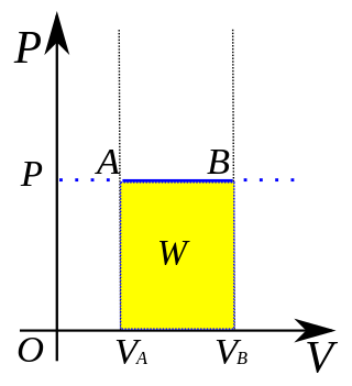
In thermodynamics, an isobaric process is a type of thermodynamic process in which the pressure of the system stays constant: ΔP = 0. The heat transferred to the system does work, but also changes the internal energy (U) of the system. This article uses the physics sign convention for work, where positive work is work done by the system. Using this convention, by the first law of thermodynamics,

<span class="mw-page-title-main">Reversible process (thermodynamics)</span> Thermodynamic process whose direction can be reversed to return the system to its original state

In thermodynamics, a reversible process is a process, involving a system and its surroundings, whose direction can be reversed by infinitesimal changes in some properties of the surroundings, such as pressure or temperature.

<span class="mw-page-title-main">Compressed-air energy storage</span> Method for matching variable production with demand

Compressed-air energy storage (CAES) is a way to store energy for later use using compressed air. At a utility scale, energy generated during periods of low demand can be released during peak load periods.

<span class="mw-page-title-main">Compressor</span> Machine to increase pressure of gas by reducing its volume

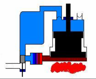
A compressor is a mechanical device that increases the pressure of a gas by reducing its volume. An air compressor is a specific type of gas compressor.

A refrigerator designed to reach cryogenic temperatures is often called a cryocooler. The term is most often used for smaller systems, typically table-top size, with input powers less than about 20 kW. Some can have input powers as low as 2–3 W. Large systems, such as those used for cooling the superconducting magnets in particle accelerators are more often called cryogenic refrigerators. Their input powers can be as high as 1 MW. In most cases cryocoolers use a cryogenic fluid as the working substance and employ moving parts to cycle the fluid around a thermodynamic cycle. The fluid is typically compressed at room temperature, precooled in a heat exchanger, then expanded at some low temperature. The returning low-pressure fluid passes through the heat exchanger to precool the high-pressure fluid before entering the compressor intake. The cycle is then repeated.

<span class="mw-page-title-main">Ericsson cycle</span>

The Ericsson cycle is named after inventor John Ericsson who designed and built many unique heat engines based on various thermodynamic cycles. He is credited with inventing two unique heat engine cycles and developing practical engines based on these cycles. His first cycle is now known as the closed Brayton cycle, while his second cycle is what is now called the Ericsson cycle. Ericsson is one of the few who built open-cycle engines, but he also built closed-cycle ones.

<span class="mw-page-title-main">Thermodynamic process</span> Passage of a system from an initial to a final state of thermodynamic equilibrium

Classical thermodynamics considers three main kinds of thermodynamic process: (1) changes in a system, (2) cycles in a system, and (3) flow processes.

<span class="mw-page-title-main">Thermodynamic cycle</span> Linked cyclic series of thermodynamic processes

A thermodynamic cycle consists of linked sequences of thermodynamic processes that involve transfer of heat and work into and out of the system, while varying pressure, temperature, and other state variables within the system, and that eventually returns the system to its initial state. In the process of passing through a cycle, the working fluid (system) may convert heat from a warm source into useful work, and dispose of the remaining heat to a cold sink, thereby acting as a heat engine. Conversely, the cycle may be reversed and use work to move heat from a cold source and transfer it to a warm sink thereby acting as a heat pump. If at every point in the cycle the system is in thermodynamic equilibrium, the cycle is reversible. Whether carried out reversible or irreversibly, the net entropy change of the system is zero, as entropy is a state function.

<span class="mw-page-title-main">Carnot cycle</span> Idealized thermodynamic cycle

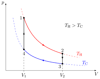
A Carnot cycle is an ideal thermodynamic cycle proposed by French physicist Sadi Carnot in 1824 and expanded upon by others in the 1830s and 1840s. By Carnot's theorem, it provides an upper limit on the efficiency of any classical thermodynamic engine during the conversion of heat into work, or conversely, the efficiency of a refrigeration system in creating a temperature difference through the application of work to the system.

<span class="mw-page-title-main">Heat pump and refrigeration cycle</span> Mathematical models of heat pumps and refrigeration

Thermodynamic heat pump cycles or refrigeration cycles are the conceptual and mathematical models for heat pump, air conditioning and refrigeration systems. A heat pump is a mechanical system that allows for the transmission of heat from one location at a lower temperature to another location at a higher temperature. Thus a heat pump may be thought of as a "heater" if the objective is to warm the heat sink, or a "refrigerator" or “cooler” if the objective is to cool the heat source. In either case, the operating principles are similar. Heat is moved from a cold place to a warm place.

<span class="mw-page-title-main">Vuilleumier cycle</span>

TheVuilleumier cycle was patented by a Swiss-American engineer named Rudolph Vuilleumier in 1918. The purpose of Vuilleumier's machine was to create a heat pump that would use heat at high temperature as energy input. The Vuilleumier cycle...

utilize[s] working gas expansion and compression at three variable volume spaces in order to pump heat from a low to a moderate temperature level. The interesting characteristic of the Vuilleumier machine is that the induced volume variations are realized without the use of work, but thermally. This is the reason why it has a potential to operate at modern applications where the pollution of the environment is not a choice. It is a perfect candidate for such applications, as it consists only of metallic parts and inert gas. Using these units for heating and cooling buildings, large energy savings can be accomplished as they can be operated at small scale in common buildings or at large scale providing heat power to entire building blocks without using fossil fuels. The use of Vuilleumier machines for industrial applications or inside vehicles is also a feasible option. Another field where these machines have already been involved is cryogenics, as they are also able to provide refrigeration at very low temperatures like the very similar and well-known Stirling refrigerators.

<span class="mw-page-title-main">Applications of the Stirling engine</span> Practical uses for Sterling engine technology

Applications of the Stirling engine range from mechanical propulsion to heating and cooling to electrical generation systems. A Stirling engine is a heat engine operating by cyclic compression and expansion of air or other gas, the "working fluid", at different temperature levels such that there is a net conversion of heat to mechanical work. The Stirling cycle heat engine can also be driven in reverse, using a mechanical energy input to drive heat transfer in a reversed direction.

References

  1. Robert Sier (1999). Hot air caloric and stirling engines. Vol.1, A history (1st Edition (Revised) ed.). L.A. Mair. ISBN   0-9526417-0-4.
  2. Organ, "The Regenerator and the Stirling Engine", p. xxii, Foreword by Urieli
  3. Organ, "The Regenerator and the Stirling Engine", p. 7
  4. Jakob, M. (1957) Heat Transfer II John Wiley, New York, USA and Chapman and Hall, London, UK
  5. A. Romanelli Alternative thermodynamic cycle for the Stirling machine, American Journal of Physics 85, 926 (2017)
  6. 1 2 Organ, "The Regenerator and the Stirling Engine"
  7. Israel Urieli (Dr. Iz), Associate Professor Mechanical Engineering: Stirling Cycle Machine Analysis Archived 2010-06-30 at the Wayback Machine