3D fold evolution

Last updated
basic structure of a fold Fold terminology-01.jpg
basic structure of a fold
Fig.1: 3D fold growth under compressional stress. Yellow, orange and red color represents elevation, in which lighter color refers to higher elevation. 3d fold growth mod 2.gif
Fig.1: 3D fold growth under compressional stress. Yellow, orange and red color represents elevation, in which lighter color refers to higher elevation.

In geology, 3D fold evolution is the study of the full three dimensional structure of a fold as it changes in time. A fold is a common three-dimensional geological structure that is associated with strain deformation under stress. Fold evolution in three dimensions can be broadly divided into two stages, namely fold growth and fold linkage. The evolution depends on fold kinematics, [1] Fold mechanism, [2] [3] as well as a reporting of the history behind folds and relationships by which fold age is understood. [4] There are several ways to reconstruct the evolution progress of folds, notably by using depositional evidence, geomorphological evidence and balanced restoration. [5] [6]

Contents

3D fold growth

Fig.2: Map View (upper) and cross-sectional view (lower) of fold growth Map and cxn view growth.gif
Fig.2: Map View (upper) and cross-sectional view (lower) of fold growth

Under compressional stress, folds grow in all three dimensions, including vertical fold amplification and lateral fold propagation, both along fold crest and perpendicular to fold crests. Three-dimensional fold growth can be observed in areas like the Zagros Mountains in Iraq and Iran [6] as well as Wheeler Ridge in California, United States. [7]

Fold structure

The vertical dimension of a fold can be described as an amplitude. The horizontal dimension of a fold can by described by wavelength and hinge line of a fold. As a fold grows in three-dimension, amplitude, wavelength and the length of the hinge line will increase. [8]

Sheath fold

A diagram showing the structure and evolution of a sheath fold Sheath Fold-01.jpg
A diagram showing the structure and evolution of a sheath fold

Sheath folds form in areas where rocks react differently to simple shear, due to variations in competence across layers. The hinge line is severely bent in sheath fold. [9]

Fold kinematics

Under force, rock strata buckle occurs by one of two kinematic processes, either by hinge migration or by limb rotation. [1]

Hinge migration

Fig.3: Illustration of twofold kinematics, hinge migration(left) and limb rotation(right) and their respective growth strata pattern. Hinge migration vs limb rotation mod 2.jpg
Fig.3: Illustration of twofold kinematics, hinge migration(left) and limb rotation(right) and their respective growth strata pattern.

A fold hinge can migrate when strata are folded by hinge migration but the hinge is fixed when strata are folded by limb rotation. [10] At least one of the fold hinges in the whole fold structure is mobile during three dimensional fold growth. [1] [11] For example, indicated by kinematic models, the structure of a fault-propagation folds should contain three anticlines/synclines with migrating hinges and 1 anticline with fixed hinge limb rotation. [1] [12]

Hinge migration can be distinguished from limb rotation by several structural and geomorphological features. [1]

Growth strata, also known as syntectonic strata, are sedimentary layers that are deposited at the same time as folding. These layers are characterized by decreasing thickness of strata towards crest of an anticline(fig 1). They exist in various geometric patterns. The variation in geometric patterns can be attributed to fold kinematics, rate of uplift and sedimentation rate. [1] [10] [13]

A knickpoint is a morphological term for a section of a present or abandoned river valley that shows an abrupt change in slope, and can be attributed to differential erosion or structural deformation. They are usually associated with waterfalls and lakes. [14]

For the definition of wind gaps, please see subsection #streams deflected around the nose of fold.

Hinge Migration VS Limb Rotation
Structural and geomorphological featuresHinge MigrationLimb Rotation
Pattern of growth strata [1] [10] Shoulder-shapedGradual tapering
Hinge deformation [1] At limb and hingeOnly near fixed hinge
Knickpoint [1] Shifting along direction of hinge migrationFixed position
Wind gaps [1] [15] Multiple wind gaps can be formed from a single riverUnlikely to form more than one wind gaps

Fold mechanism

Folds that may experience prolonged 3D growth can be divided into two groups according to their causes, namely detachment fold and forced fold. They are mainly differentiated by the presence of major fault control on fold structure in forced folds, and the absence of it in detachment folds. Fold causes that do not contribute to significant fold growth in all three dimensions, such as en-echelon folds, drag folds and rollover anticline are not in these groups. [16] [17] Understanding the evolution of folds is important because it helps petroleum geologists to gain a better understanding on the distribution of structural traps of hydrocarbon. [18] [19] [20]

Detachment fold

Fig.4: A short demonstration of the concept of evolution of detachment fold. Table: competent rock unit; Paper: incompetent rock unit; Decollement: interface between paper and table. Detachment fold demonstration.gif
Fig.4: A short demonstration of the concept of evolution of detachment fold. Table: competent rock unit; Paper: incompetent rock unit; Decollement: interface between paper and table.
Fig.5: A model of detachment fold. Decollement can either develop along bedding in the incompetent layer, as shown here, or along the interface of competent and incompetent layer. Detachment fold.png
Fig.5: A model of detachment fold. Decollement can either develop along bedding in the incompetent layer, as shown here, or along the interface of competent and incompetent layer.

As shown in the visual analogy for detachment folds in fig 4, folds are found in rock strata above the decollement (paper: incompetent) while rock strata below it (table: competent, if it deforms it will fracture) remains undeformed, as shortening strain is concentrated at the rock strata above decollement. [3] [21] [22] In a setting in which overlapping strata acquires contrasting competency, a decollement (interface between paper and table) is usually found along strata in competent rock unit (such as sandstone) or along the interface of competent and incompetent rock unit (such as an evaporite). A fold acquires higher amplitude, longer wavelength and broader width when rock strata above the decollement are subjected to shortening stress parallel to, or at a low angle to the strata. Apart from stress parameters, contrast of competency across strata and variation of displacement along the decollement are the main factors contributing to fold geometry and three dimensional growth pattern. [23] [24]

Fig.6: A model of a fault-propagation fold, an example of forced fold. Note that folding in the overlying sedimentary strata is controlled by faulting in the basement rocks. Forced fold new-01.jpg
Fig.6: A model of a fault-propagation fold, an example of forced fold. Note that folding in the overlying sedimentary strata is controlled by faulting in the basement rocks.

Forced fold

Two common types of forced folds are, namely, fault-bend fold and fault-propagation fold. Folding occurs above the hanging wall of a fold ramp in a fault-bend fold, while folding occurs above the truncation of a thrust fault(fault tip) in a fault-propagation fold. They are usually highly asymmetric with one side of the limb much steeper than the other side. [3] Shortening stress is usually at a high angle to the strata and is concentrated along the slipping plane and in the hanging wall of the thrust fault. The fold acquires higher amplitude, longer wavelength and broader width as rock slips along the fault plane of the underlying coeval thrust fault, casting major influence on the three dimensional growth of the fold. Therefore, forced folds are controlled by the fault structure in the basement rocks along planar or listric fault surfaces. [3] [25] The amount of fault displacement would control the amplitude of a fold, the lateral growth of fault would implies lateral growth of fold and fault linkage implies fold linkage on the surface. [26] When compared to detachment folds, contrasting competency across strata is not as pronounced [23] and the tectonic environments that they are found in are often more diverse. [3]

Fig. 7: An evolutionary diagram on fault-propagation fold. Note that the fault diminishes gradually towards the top. Fault propagation fold.gif
Fig. 7: An evolutionary diagram on fault-propagation fold. Note that the fault diminishes gradually towards the top.
Fig. 8: An animation on the evolution of a fault-bend fold, Note that 2 anticlines and synclines are formed at the final stage of the progression. Fault-bend fold mod.gif
Fig. 8: An animation on the evolution of a fault-bend fold, Note that 2 anticlines and synclines are formed at the final stage of the progression.

A detachment fold can evolve into a forced fold when shortening stress exceeds the maximum strength of rock, and as a result the decollement may propagate upwards towards the anticlinal core and fault the detachment fold. [24] The resultant structure poses characteristics of both detachment fold and fault propagation fold. [27] An exemplar structure of this kind can be found in Mississippi Fan fold belt in Gulf of Mexico. [28]

Identification of 3D fold growth

Fold growth in cross-sectional, across fold-axis dimension

Modelling of the kinematic evolution of folds in cross-sectional view is usually based on one of the following schemes: balanced restoration, forward kinematic modelling or a combination of the two. [12] [29] [30] [31]

Fold growth in lateral dimension

Section restoration in all three dimension can only be done by highly specialized software and is mainly used for studies in hydrocarbon. [32]

Alternatively, geomorphological evidences, especially drainage features, can be used to determine the lateral propagation direction of fold growth. There are 6 main criteria for identifying lateral fold growth: [6] [15] [26] [33] [7]

Degree of surface dissection and drainage density along fold crest

Drainage density (=total river length/area of drainage basin) and degree of surface dissection decreases along with propagation direction of a fold. Higher drainage density and greater degree of surface dissection in a particular part of a fold segment corresponds to the higher maturity of that part, which can be inferred as that that part has been subjected to erosion for a longer time period after uplift. Hence, it experienced uplift relative earlier than other parts of the fold [33] [34] . Mathematical analysis of the maturity of drainage which take into the account of stream length and stream order can also be used to establish the relative ages of different drainage basins. [34] [35]

Progressive change of soil profile

Older sections of a fold experience more erosion and therefore have a different soil profile compared to their younger counterparts. Soil profiles can be classified into different stages of development according to morphological stages of carbonate horizons in soil, mass of secondary carbonate, iron oxide content, clay content, thickness of clay-film and color brightness of soil, [7] and thus establishes lateral growth direction of the fold. Furthermore, carbon-14 or uranium-series dating of soil materials would set time constraint on certain parts of the fold and therefore helps fixing the rate of lateral fold growth. [7]

Nevertheless, this criterion of comparison is based on an assumption that time is the only significant factor contributing to the differences of soil profiles across different parts of a fold, and excludes other factors for variation such as parent materials of soil, climate, vegetation and initial topography. [7] Therefore, the progressive change in soil profile is more of a secondary evidence of lateral fold growth. [7]

Structural relief

Structural elevation along fold crest should decrease along the growth direction of a fold because the older part of a fold experiences more uplift than their younger counterpart [33] [7] . However, this can be strongly misleading in active erosional environment where erosion rather than uplift due to fold growth is the dominant shaping force of the landscape and as a result can only be used as secondary evidence of fold growth.

Fig. 9: Asymmetric forked drainage pattern. The diagram shows drainage pattern (a) before and (b) after lateral fold growth, as well as a 3D view of asymmetric drainage pattern. Strong erosion of river onto bedrock has preserved the old drainage valley at upper course and thus some of the first-generation drainage channels are inherited and linked with the present drainage channels. Modified after Ramsey (2008). Asymmetric folk drainage mod mod-01.jpg
Fig. 9: Asymmetric forked drainage pattern. The diagram shows drainage pattern (a) before and (b) after lateral fold growth, as well as a 3D view of asymmetric drainage pattern. Strong erosion of river onto bedrock has preserved the old drainage valley at upper course and thus some of the first-generation drainage channels are inherited and linked with the present drainage channels. Modified after Ramsey (2008).

Characteristic drainage pattern on the slope of anticline

An asymmetric forked drainage pattern forms during lateral growth of a fold. The direction along which drainage channels 'bend away' from the fold crest is the direction of lateral fold growth(fig. 7) [6] [15] [26] . Imagine the following situation: at an early stage of folding and near the fold tip, river flows approximately along the fold crests towards the end of a fold as river tends to flow down the slope of maximum gradient. As folding continues, that point is no longer located at the fold tip as the fold grows laterally. As the point is uplifted to a higher elevation, the slope of maximum gradient is no longer along the fold crest, but becomes the distance from fold hinge towards the other end of fold limb, which is approximately perpendicular to the original orientation. As a result, the new generation of river flows perpendicular to the fold crest along the fold limbs. Because of strong river erosion in the upper course, some of the drainage channels of the earlier stage are deeply incised into bedrock and therefore river continues to flow along these upper parts of old channels that do not follow the maximum slope gradient. As a result, combining the fold-crest-parallel direction of flow in the upper part of drainage channels (which are inherited from the early stages of deformation) and the fold-crest-perpendicular direction of flow in the middle and lower of drainage channels, an asymmetric drainage pattern that resembles a bent fork results. [6] [15] This criterion is a strong evidence for lateral fold growth.

Streams deflected around the nose of fold

Fig.10: Stream got deflected to flow sub-parallel to fold crest and bend around the tip of the growing fold, hinting a westward direction of lateral fold growth. Image: Landsat ETM+7 Deflected streams lateral fold growth.jpg
Fig.10: Stream got deflected to flow sub-parallel to fold crest and bend around the tip of the growing fold, hinting a westward direction of lateral fold growth. Image: Landsat ETM+7
Fig.11: Schematic diagram showing deflection of a river during lateral fold growth. Blue line: river; Light blue line: wind gap Deflected stream schematic.gif
Fig.11: Schematic diagram showing deflection of a river during lateral fold growth. Blue line: river; Light blue line: wind gap

Streams are deflected as they meet uplifted rocks and flow along the boundary of the fold, which is parallel or sub-parallel to fold axis [6] [15] [33] and the curvature of the deflected stream convex towards the direction of lateral fold growth along fold crest. [34]

There are two possible scenarios when the path of a stream is blocked by an uplifted block of rock. First scenario: the stream poses stream power that is high enough to cut through the uplifted rocks, so that the river course will not be significantly altered. A channel is opened in the uplifted rocks due to erosion, a landform known as water gap. It continues to flow until the rock is further uplifted and the river no longer has enough erosive power to cut through it, leading to the second scenario. Second scenario: the stream does not have enough erosive power to cut through the rocks, so it deflected to flow along the boundary of the uplifted block as aforementioned. The abandoned river channel is known as wind gap. From here, the river either flows along the boundary of the fold and bends around the fold tip, or it may cut through the rocks at some points despite the block, due to either, acquisition of enough stream power through stream capture of small tributaries along its flow, or the presence of a particularly weak spot in the rock. [6] [15] In either way the river continues to flow until further uplift of rocks makes the rock too difficult for the river to cut through, which results in, again, the deflection of the channel and formation of a new wind gap.

Wind gaps

Fig. 12: The upper diagram shows a cross-section A-A' along the fold crests of two growing folds. The lower part shows a map view of the region. WG=wind gap. Red arrows: direction of lateral fold growth; Wind gap elevation decreases along lateral fold growth direction and curvatures of wind gaps convex towards lateral fold growth direction. The 2 fold segments grow towards each other and merge. Asymmetric forked drainage patterns are delineated on the fold segments. Modified from Hetzel (2004), He and Li (2009) and Ramsey (2008). Decreasing wind gap elevation-01 mod.jpg
Fig. 12: The upper diagram shows a cross-section A-A' along the fold crests of two growing folds. The lower part shows a map view of the region. WG=wind gap. Red arrows: direction of lateral fold growth; Wind gap elevation decreases along lateral fold growth direction and curvatures of wind gaps convex towards lateral fold growth direction. The 2 fold segments grow towards each other and merge. Asymmetric forked drainage patterns are delineated on the fold segments. Modified from Hetzel (2004), He and Li (2009) and Ramsey (2008).
Fig. 13: Idealized river profiles of water gap and wind gap respectively. Yellow line - wind gap; Blue line and green line - water gap. Note that this is a highly idealized diagram and the actual profile of both wind and water gap should be much more rugged and irregular, though the average trend will be similar to the diagram. Based on He and Li (2009). Wing gap river gap longitudinal profile.jpg
Fig. 13: Idealized river profiles of water gap and wind gap respectively. Yellow line – wind gap; Blue line and green line – water gap. Note that this is a highly idealized diagram and the actual profile of both wind and water gap should be much more rugged and irregular, though the average trend will be similar to the diagram. Based on He and Li (2009).

Elevation of wind gaps decreases along the growth direction of fold and curvature of curved wind gaps convex towards the growth direction of the fold. [15] [26] [33] [36] Multiple wind gaps can be formed from a single river if there is continuous lateral fold growth and the river keeps being deflected, by abandoning its earlier channel and forming a new one around the outside of the developing fold. [33] In a topographic profile along fold crest, wind gaps appears as deep, narrow v-shaped valley. The incision depth of a wind gap correspond to the period of active river erosion before the channel was abandoned, i.e. the duration of its state of being a river or water gap. Since the time of abandonment of an old river channel(time of formation of a new wind gap) is the time of formation of a new river channel and the start of erosion in the new channel, the base elevation of a wind gap would approximately equals to the surface elevation of its successor, provided that they were formed from the same river. [36] Therefore, the elevation of wind gaps must always decrease along the direction of lateral fold growth along fold crest, which is one of the strongest, although not decisive, evidence of the characteristics of fold growth. [33] As former deflected streams, some of the wind gaps may show curvature that convex towards the direction of lateral fold growth.

In a Digital Elevation Model(DEM), the longitudinal profile of a wind gap shows a convex-upwards trend and that of a water gap shows a concave-upwards or linear trend. [26]

None of the single aforementioned methodologies is decisive on determining 3D fold growth and a combination of methodologies should be used, because similar morphology can be produced by limb rotation and differential erosion across strata of varying competency, [15] which do not implicate three-dimensional fold growth.

Wheeler Ridge, California

Fig. 14 Left: Sentinel Satellite Image of area of Wheeler Ridge, CA. Right: Showing water gaps and wind gap at the eastern part of Wheeler Ridge anticline and topographic profile A-B across the fold crest. Brown line: fold hinge; Blue line: river/water gap; Brown line: wind gap Wheeler ridge rivers-01-01.jpg
Fig. 14 Left: Sentinel Satellite Image of area of Wheeler Ridge, CA. Right: Showing water gaps and wind gap at the eastern part of Wheeler Ridge anticline and topographic profile A-B across the fold crest. Brown line: fold hinge; Blue line: river/water gap; Brown line: wind gap

Located at southern California, Wheeler Ridge anticline is an east–west trending fault-bend fold, [38] and is part of Pleito-Wheeler Ridge thrust fault system. [7] Structural deformation in the area has been active since late Pleistocene, resulting in significant three-dimensional fold growth. [7]

The eastern end of the anticline has been experiencing fold growth towards the east-southeast. [7]

Firstly, the structural elevation of eastern Wheeler Ridge decreases from the west to east, [7] suggesting that the eastern part of the examined section is uplifted and exposed to erosion at a later time than the western part of the examined section. Thereby it supports a west-to-east fold growth direction

Second, the main flowing river channels show a curvature that bends towards the east-southeast. The curvature seems to a result of gradual uplift of rocks towards the east-southeast and shows resemblance to the patterns of deflected streams during lateral fold growth. Under this assumption, this evidence supports the growth of fold towards the east-southeast. [7]

Third, the abandonment of old river channels (formation of wind gap) can be seen in a topographic profile across ridge crest. [7] As shown in fig.12, the base elevation of the wind gap approximately corresponds to the surface elevation of water gap 1, indicating that the original river channel along the wind gap was abandoned at the same time as water starts to flow in water gap 1 and therefore the two are probably formed from the singer river. It seems that the river originally flowing in the wind gap was deflected due to uplifting and flow along water gap 1 instead. Therefore, there is a strong evidence supporting that fold grows laterally towards east-southeast.

Forth, soil analysis indicates a high level of soil development at the western part of the examined section indicates, and the level of soil development gradually decreases towards the east. [7] It is suggested that western part of the examined area is of an older age comparing to the eastern part, and therefore the fold grows from west to east.

Fold linkage

Orientation of linkage

In an area affected by regional stress, most of the faults and folds are aligned along strike. [4] In forced folds, linkage of folds is strongly associated with linkage of the underlying faults. [15] Growth and displacement of faults are affected by not only the far-field stress of the region but also the position of faults relative to each other. [39] This is a result of a reloading positive feedback mechanism, which suggests that the stress build-up in the population of faults that are aligned along strike are much faster than those located in stress shadow (i.e. transverse to the main alignments), and thus the higher frequency of rupture and growth rates in faults that are optimally aligned. [4] [39] [40] [41] Conversely, the faults that are located in stress shadow are relaxed and have a lower frequency of rupture and growth rates. As localization of deformation among faults continues, some faults may concentrate the stress and upon linking with other faults form a main fault that accommodates most of the displacement in the region. [4] On the other hand, the faults that orient in the stress shadow will decrease in growth rates and even become inactive in the long term. [4] As a result, in a region with pervasive compressional stress, two merged fold segments are usually aligned along-strike, as the folds would probably be rendered inactive if they are not aligned in such favorable ways. [15]

Mode of linkage

Linear LinkageEn-echelon LinkageNo Linkage
Fig. 15
Brown line: fold hinge line;
Red arrow: direction of lateral fold growth. Linear fold linkage.gif
Fig. 15
Brown line: fold hinge line;
Red arrow: direction of lateral fold growth.
Fig. 16
Brown line: fold hinge line;
Red arrow: direction of lateral fold growth. Oblique fold linkage.gif
Fig. 16
Brown line: fold hinge line;
Red arrow: direction of lateral fold growth.
Fig. 17
Brown line: fold hinge line;
Brown arrow: plunging direction of fold;
Red arrow: direction of lateral fold growth;
Amid: relative height of the horizontal middle of the area;
D: perpendicular distance between hinge lines of the approaching folds. No fold linkage mod mod.gif
Fig. 17
Brown line: fold hinge line;
Brown arrow: plunging direction of fold;
Red arrow: direction of lateral fold growth;
Amid: relative height of the horizontal middle of the area;
D: perpendicular distance between hinge lines of the approaching folds.
Resultant landforms
A linear saddle that is aligned with the fold axis of the embryonic folds forms in between approaching folds [5] [6] A curved saddle forms in between the approaching folds [6] Embryonic fold segments grow past each other without mechanical interaction
Overall structure
A continuous cylindrical fold [6] aligning perpendicular to the regional tectonic force that resembles a Type 1 refold structure. [6] It can be confused with a single growing embryonic fold with huge fold axial lengthA single continuous cylindrical anticlinal structure with bent fold hinge around the point of linkage, resembling a Type 2 refold structure [6] Two oppositely plunging parallel anticlinal fold trains and a syncline form [6]
Remarks
The overall structure can be easily confused with a single growing embryonic fold with huge fold axial length. [6] Embryonic fold segments grow in a direction perpendicular to the regional tectonic force.Growing embryonic fold segments align in a stepping manner and join obliquely. [5] [6] Embryonic fold segments grow in a direction perpendicular to the regional tectonic force.Embryonic fold segments grow in a direction perpendicular to the regional tectonic force.

Identification of fold linkage

Amid, relative height of surface in the horizontal middle of the surface in the area of approaching fold tips, is useful for defining the status of two approaching structures in the spectrum from no linkage to linear or en-echelon linkage. [5] Relative height is defined as the surface elevation of the point of interest minus the average surface elevation of the area of the approaching fold tips (see fig.15). [5]

If Amid>0, linkage is present.

If Amid<0, linkage is absent.

If Amid~0, the structure is in the transitional zone between linkage and no-linkage.

After determining the presence of linkage between twofold segments, it is possible to identify linear linkage between the segments by a straight antiformal saddle in between the two main folds. [5] [6] For an en-echelon linkage, the main folds of the segments would be linked by a curved antiformal saddle in between. [5] [6]

Further reading

Related Research Articles

<span class="mw-page-title-main">Thrust fault</span> Type of reverse fault that has a dip of 45 degrees or less

A thrust fault is a break in the Earth's crust, across which older rocks are pushed above younger rocks.

<span class="mw-page-title-main">Cumberland Mountains</span> Mountain range in the southeastern United States

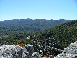
The Cumberland Mountains are a mountain range in the southeastern section of the Appalachian Mountains. They are located in western Virginia, southwestern West Virginia, the eastern edges of Kentucky, and eastern middle Tennessee, including the Crab Orchard Mountains. Their highest peak, with an elevation of 4,223 feet (1,287 m) above mean sea level, is High Knob, which is located near Norton, Virginia.

<span class="mw-page-title-main">Los Angeles Basin</span> Sedimentary basin located along the coast of southern California

The Los Angeles Basin is a sedimentary basin located in Southern California, in a region known as the Peninsular Ranges. The basin is also connected to an anomalous group of east-west trending chains of mountains collectively known as the Transverse Ranges. The present basin is a coastal lowland area, whose floor is marked by elongate low ridges and groups of hills that is located on the edge of the Pacific Plate. The Los Angeles Basin, along with the Santa Barbara Channel, the Ventura Basin, the San Fernando Valley, and the San Gabriel Basin, lies within the greater Southern California region. The majority of the jurisdictional land area of the city of Los Angeles physically lies within this basin.

<span class="mw-page-title-main">Fold (geology)</span> Stack of originally planar surfaces

In structural geology, a fold is a stack of originally planar surfaces, such as sedimentary strata, that are bent or curved ("folded") during permanent deformation. Folds in rocks vary in size from microscopic crinkles to mountain-sized folds. They occur as single isolated folds or in periodic sets. Synsedimentary folds are those formed during sedimentary deposition.

Flynn Creek crater is an impact crater situated in Jackson County, Tennessee, approximately 8 km south of Gainesboro.

<span class="mw-page-title-main">Diastrophism</span> Deformation of the Earths crust

Diastrophism is the process of deformation of the Earth's crust which involves folding and faulting. Diastrophism can be considered part of geotectonics. The word is derived from the Greek διαστροϕή diastrophḗ 'distortion, dislocation'.

<span class="mw-page-title-main">Anticline</span> In geology, an anticline is a type of fold that is an arch-like shape

In structural geology, an anticline is a type of fold that is an arch-like shape and has its oldest beds at its core, whereas a syncline is the inverse of an anticline. A typical anticline is convex up in which the hinge or crest is the location where the curvature is greatest, and the limbs are the sides of the fold that dip away from the hinge. Anticlines can be recognized and differentiated from antiforms by a sequence of rock layers that become progressively older toward the center of the fold. Therefore, if age relationships between various rock strata are unknown, the term antiform should be used.

<span class="mw-page-title-main">Joint (geology)</span> Type of fracture in rock

A joint is a break (fracture) of natural origin in a layer or body of rock that lacks visible or measurable movement parallel to the surface (plane) of the fracture. Although joints can occur singly, they most frequently appear as joint sets and systems. A joint set is a family of parallel, evenly spaced joints that can be identified through mapping and analysis of their orientations, spacing, and physical properties. A joint system consists of two or more intersecting joint sets.

<span class="mw-page-title-main">Dome (geology)</span> Geological deformation structure

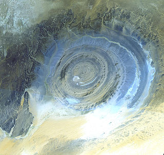
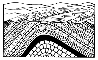
A dome is a feature in structural geology where a circular part of the Earth's surface has been pushed upward, tilting the pre-existing layers of earth away from the center. In technical terms, it consists of symmetrical anticlines that intersect each other at their respective apices. Intact, domes are distinct, rounded, spherical-to-ellipsoidal-shaped protrusions on the Earth's surface. A slice parallel to Earth's surface of a dome features concentric rings of strata. If the top of a dome has been eroded flat, the resulting structure in plan view appears as a bullseye, with the youngest rock layers at the outside, and each ring growing progressively older moving inwards. These strata would have been horizontal at the time of deposition, then later deformed by the uplift associated with dome formation.

The Lewis Overthrust is a geologic thrust fault structure of the Rocky Mountains found within the bordering national parks of Glacier in Montana, United States and Waterton Lakes in Alberta, Canada. The structure was created due to the collision of tectonic plates about 59-75 million years ago that drove a several mile thick wedge of Precambrian rock 50 mi (80 km) eastwards, causing it to overlie softer Cretaceous age rock that is 1300 to 1400 million years younger.

<span class="mw-page-title-main">Décollement</span> Geological feature

Décollement is a gliding plane between two rock masses, also known as a basal detachment fault. Décollements are a deformational structure, resulting in independent styles of deformation in the rocks above and below the fault. They are associated with both compressional settings and extensional settings.

For other "River Knobs", see River Knobs (disambiguation).

<span class="mw-page-title-main">Homocline</span> Geological structure in which rock strata dip uniformly in a single direction

In structural geology, a homocline or homoclinal structure, is a geological structure in which the layers of a sequence of rock strata, either sedimentary or igneous, dip uniformly in a single direction having the same general inclination in terms of direction and angle. A homocline can be associated with either one limb of a fold, the edges of a dome, the coast-ward tilted strata underlying a coastal plain, slice of thrust fault, or a tilted fault block. When the homoclinal strata consists of alternating layers of rock that vary hardness and resistance to erosion, their erosion produces either cuestas, homoclinal ridges, or hogbacks depending on the angle of dip of the strata. On a topographic map, the landfroms associated with homoclines exhibit nearly parallel elevation contour lines that show a steady change in elevation in a given direction. In the subsurface, they characterize by parallel structural contour lines.

<span class="mw-page-title-main">Erosion and tectonics</span> Interactions between erosion and tectonics and their implications

The interaction between erosion and tectonics has been a topic of debate since the early 1990s. While the tectonic effects on surface processes such as erosion have long been recognized, the opposite has only recently been addressed. The primary questions surrounding this topic are what types of interactions exist between erosion and tectonics and what are the implications of these interactions. While this is still a matter of debate, one thing is clear, Earth's landscape is a product of two factors: tectonics, which can create topography and maintain relief through surface and rock uplift, and climate, which mediates the erosional processes that wear away upland areas over time. The interaction of these processes can form, modify, or destroy geomorphic features on Earth's surface.

<span class="mw-page-title-main">Detachment fold</span>

A detachment fold, in geology, occurs as layer parallel thrusting along a decollement develops without upward propagation of a fault; the accommodation of the strain produced by continued displacement along the underlying thrust results in the folding of the overlying rock units. As a visual aid, picture a rug on the floor. By placing your left foot on one end and pushing towards the other end of the rug, the rug slides across the floor (decollement) and folds upward. Figure 1, is a generalized representation of the geometry assumed by a detachment fault.

<span class="mw-page-title-main">Zagros fold and thrust belt</span> Geologic zone

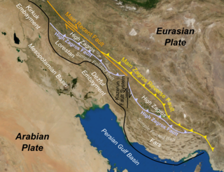
The Zagros fold and thrust belt is an approximately 1,800-kilometre (1,100 mi) long zone of deformed crustal rocks, formed in the foreland of the collision between the Arabian Plate and the Eurasian Plate. It is host to one of the world's largest petroleum provinces, containing about 49% of the established hydrocarbon reserves in fold and thrust belts (FTBs) and about 7% of all reserves globally.

A river anticline is a geologic structure that is formed by the focused uplift of rock caused by high erosion rates from large rivers relative to the surrounding areas. An anticline is a fold that is concave down, whose limbs are dipping away from its axis, and whose oldest units are in the middle of the fold. These features form in a number of structural settings. In the case of river anticlines, they form due to high erosion rates, usually in orogenic settings. In a mountain building setting, like that of the Himalaya or the Andes, erosion rates are high and the river anticline's fold axis will trend parallel to a major river. When river anticlines form, they have a zone of uplift between 50-80 kilometers wide along the rivers that form them.

<span class="mw-page-title-main">El Tigre Fault</span>

The El Tigre Fault is a 120 km long, roughly north-south trending, major strike-slip fault located in the Western Precordillera in Argentina. The Precordillera lies just to the east of the Andes mountain range in South America. The northern boundary of the fault is the Jáchal River and its southern boundary is the San Juan River. The fault is divided into three sections based on fault trace geometry, Northern extending between 41–46 km in length, Central extending between 48–53 km in length, and Southern extending 26 km in length. The fault displays a right-lateral (horizontal) motion and has formed in response to stresses from the Nazca Plate subducting under the South American Plate. It is a major fault with crustal significance. The Andes Mountain belt trends with respect to the Nazca Plate/South American Plate convergence zone, and deformation is divided between the Precordilleran thrust faults and the El Tigre strike-slip motion. The El Tigre Fault is currently seismically active.

<span class="mw-page-title-main">Growth fault</span>

Growth faults are syndepositional or syn-sedimentary extensional faults that initiate and evolve at the margins of continental plates. They extend parallel to passive margins that have high sediment supply. Their fault plane dips mostly toward the basin and has long-term continuous displacement. Figure one shows a growth fault with a concave upward fault plane that has high updip angle and flattened at its base into zone of detachment or décollement. This angle is continuously changing from nearly vertical in the updip area to nearly horizontal in the downdip area.

<span class="mw-page-title-main">Kutai Basin</span>

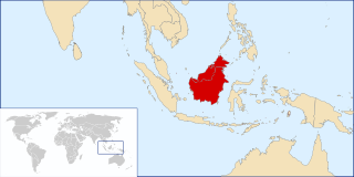
The Kutai sedimentary basin extends from the central highlands of Borneo, across the eastern coast of the island and into the Makassar Strait. With an area of 60,000 km2, and depths up to 15 km, the Kutai is the largest and deepest Tertiary age basin in Indonesia. Plate tectonic evolution in the Indonesian region of SE Asia has produced a diverse array of basins in the Cenozoic. The Kutai is an extensional basin in a general foreland setting. Its geologic evolution begins in the mid Eocene and involves phases of extension and rifting, thermal sag, and isostatic subsidence. Rapid, high volume, sedimentation related to uplift and inversion began in the Early Miocene. The different stages of Kutai basin evolution can be roughly correlated to regional and local tectonic events. It is also likely that regional climate, namely the onset of the equatorial ever wet monsoon in early Miocene, has affected the geologic evolution of Borneo and the Kutai basin through the present day. Basin fill is ongoing in the lower Kutai basin, as the modern Mahakam River delta progrades east across the continental shelf of Borneo.

References

  1. 1 2 3 4 5 6 7 8 9 10 Ahmadi, R., Ouali, J., Mercier, E., Mansy, J. L., Lanoë, B. V. V., Launeau, P., ... & Rafini, S. (2006). The geomorphologic responses to hinge migration in the fault-related folds in the Southern Tunisian Atlas. Journal of Structural Geology, 28(4), 721–728.
  2. Suppe, J., & Medwedeff, D. A. (1990). Geometry and kinematics of fault-propagation folding. Eclogae Geologicae Helvetiae, 83(3), 409–454.
  3. 1 2 3 4 5 Cosgrove, J. W. (1999). Forced folds and fractures: An introduction. Geological Society, London, Special Publications, 169(1), 1–6.
  4. 1 2 3 4 5 Cowie, P. A. (1998). A healing–reloading feedback control on the growth rate of seismogenic faults. Journal of Structural Geology, 20(8), 1075–1087.
  5. 1 2 3 4 5 6 7 Grasemann, B., & Schmalholz, S. M. (2012). Lateral fold growth and fold linkage. Geology, 40(11), 1039–1042.
  6. 1 2 3 4 5 6 7 8 9 10 11 12 13 14 15 16 17 Bretis, B., Bartl, N., & Grasemann, B. (2011). Lateral fold growth and linkage in the Zagros fold and thrust belt (Kurdistan, NE Iraq). Basin Research, 23(6), 615–630.
  7. 1 2 3 4 5 6 7 8 9 10 11 12 13 14 Keller, E. A., Zepeda, R. L., Rockwell, T. K., Ku, T. L., & Dinklage, W. S. (1998). Active tectonics at Wheeler Ridge, southern San Joaquin Valley, California. Geological Society of America Bulletin, 110(3), 298–310.
  8. RG Park (2004). "Fold axis and axial plane". Foundations of structural geology (3rd ed.). Routledge. p. 26. ISBN   0-7487-5802-X.
  9. Ghosh, S.K. (1993). Structural geology fundamentals and modern developments (1st ed.). Oxford: Pergamon Press. p. 228. ISBN   0-08-098399-5.
  10. 1 2 3 Ortner, H., Kositz, A., Willingshofer, E., & Sokoutis, D. (2010, May). Geometry of growth strata in a transpressive fold belt in field and analogue model: Gosau Group at Muttekopf, Northern Calcareous Alps, Austria. In EGU General Assembly Conference Abstracts (Vol. 12, p. 6316).
  11. Dahlstrom, C. D. (1990). Geometric Constraints Derived from the Law of Conservation of Volume and Applied to Evolutionary Models for Detachment Folding: Geologic Note:(1). AAPG Bulletin, 74(3), 336–344.
  12. 1 2 Suppe, J., Sàbat, F., Munoz, J. A., Poblet, J., Roca, E., & Vergés, J. (1997). Bed-by-bed fold growth by kink-band migration: Sant Llorenç de Morunys, eastern Pyrenees. Journal of Structural Geology, 19(3), 443–461.
  13. Ahmadi, R., Mercier, E., & Ouali, J. (2013). Growth-strata geometry in fault-propagation folds: a case study from the Gafsa basin, southern Tunisian Atlas. Swiss Journal of Geosciences, 106(1), 91–107.
  14. "Part 629 – GLOSSARY OF LANDFORM AND GEOLOGIC TERMS". USDA. Archived from the original on 2017-02-11. Retrieved 2017-02-10.
  15. 1 2 3 4 5 6 7 8 9 10 Ramsey, L. A., Walker, R. T., & Jackson, J. (2008). Fold evolution and drainage development in the Zagros mountains of Fars province, SE Iran.Basin Research, 20(1), 23–48.
  16. Cosgrove, J. W. (2000). "Forced folds and fractures: An introduction" (PDF). Geological Society. Retrieved 11 February 2017.
  17. Homza, Thomas X.; Wallace, Wesley K. (April 1995). "Geometric and kinematic models for detachment folds with fixed and variable detachment depths". Journal of Structural Geology. 17 (4): 575–588. Bibcode:1995JSG....17..575H. doi:10.1016/0191-8141(94)00077-D.
  18. Watson, M. P., Hayward, A. B., Parkinson, D. N., & Zhang, Z. M. (1987). Plate tectonic history, basin development and petroleum source rock deposition onshore China. Marine and Petroleum Geology, 4(3), 205–225.
  19. Trudgill, B. D., Fiduk, J. C., Rowan, M. G., Weimer, P., Gale, P. E., Korn, B. E., ... & Henage, L. F. (1995). The Geological Evolution and Petroleum Potential of the Deep Water Perdido Fold Belt, Alaminos Canyon, Northwestern Deep Gulf of Mexico.
  20. Roure, F., & Sassi, W. (1995). Kinematics of deformation and petroleum system appraisal in Neogene foreland fold-and-thrust belts. Petroleum Geoscience, 1(3), 253–269.
  21. Ramsay, J. G., & Huber, M. I. (1987). The techniques of modern structural geology: Folds and fractures(Vol. 2). Academic press.
  22. Homza, T. X., & Wallace, W. K. (1995). Geometric and kinematic models for detachment folds with fixed and variable detachment depths. Journal of Structural Geology, 17(4), 575–588.
  23. 1 2 Jamison, W. R. (1987). Geometric analysis of fold development in overthrust terranes. Journal of Structural Geology, 9(2), 207–219.
  24. 1 2 Mitra, S. (2002). Structural models of faulted detachment folds. AAPG bulletin, 86(9), 1673–1694.
  25. Johnson, K. M., & Johnson, A. M. (2002). Mechanical analysis of the geometry of forced-folds. Journal of Structural Geology, 24(3), 401–410.
  26. 1 2 3 4 5 He, D., & Li, J. (2009). Drainage network development and fold growth of Quilitage structural belt in the Kuqa foreland fold and thrust belt. Dizhixue Bao= Acta Geologica Sinica, 83(8), 1074–1082.
  27. Mitra, S. (2003). A unified kinematic model for the evolution of detachment folds. Journal of Structural Geology, 25(10), 1659–1673.
  28. Rowan, M. G. (1997). Three-dimensional geometry and evolution of a segmented detachment fold, Mississippi Fan foldbelt, Gulf of Mexico. Journal of Structural Geology, 19(3), 463–480.
  29. Vergés, J., Burbank, D. W., & Meigs, A. (1996). Unfolding: An inverse approach to fold kinematics. Geology, 24(2), 175–178.
  30. Mount, V. S., Suppe, J., & Hook, S. C. (1990). A Forward Modeling Strategy for Balancing Cross Sections (1). AAPG Bulletin, 74(5), 521–531.
  31. Nunns, A. G. (1991). Structural Restoration of Seismic and Geologic Sections in Extensional Regimes (1). AAPG Bulletin, 75(2), 278–297.
  32. Clarke, S. M., Burley, S. D., Williams, G. D., Richards, A. J., Meredith, D. J., & Egan, S. S. (2006). Integrated four-dimensional modelling of sedimentary basin architecture and hydrocarbon migration. Geological Society, London, Special Publications, 253(1), 185–211.
  33. 1 2 3 4 5 6 7 Keller, E. A., Gurrola, L., & Tierney, T. E. (1999). Geomorphic criteria to determine direction of lateral propagation of reverse faulting and folding.Geology, 27(6), 515–518.
  34. 1 2 3 Delcaillau, B., Carozza, J. M., & Laville, E. (2006). Recent fold growth and drainage development: the Janauri and Chandigarh anticlines in the Siwalik foothills, northwest India. Geomorphology, 76(3), 241–256.
  35. Strahler, A. N. (1952). Hypsometric (area-altitude) analysis of erosional topography. Geological Society of America Bulletin, 63(11), 1117–1142.
  36. 1 2 Hetzel, R., Tao, M., Niedermann, S., Strecker, M. R., Ivy‐Ochs, S., Kubik, P. W., & Gao, B. (2004). Implications of the fault scaling law for the growth of topography: Mountain ranges in the broken foreland of north‐east Tibet. Terra Nova, 16(3), 157–162.
  37. Sentinel Data Legal Notice
  38. "Mueller, K., & Suppe, J. (1997). Growth of Wheeler Ridge anticline, California: geomorphic evidence for fault-bend folding behaviour during earthquakes. Journal of Structural Geology, 19(3), 383–396.
  39. 1 2 Cowie, P. A., & Shipton, Z. K. (1998)
  40. Roberts, G. P., & Michetti, A. M. (2004). Spatial and temporal variations in growth rates along active normal fault systems: an example from The Lazio–Abruzzo Apennines, central Italy. Journal of Structural Geology, 26(2), 339–376.
  41. Manighetti, I., King, G. C. P., Gaudemer, Y., Scholz, C. H., & Doubre, C. (2001). Slip accumulation and lateral propagation of active normal faults in Afar. Journal of Geophysical Research: Solid Earth, 106(B7), 13667-13696.