An analog signal or analogue signal is any continuous-time signal representing some other quantity, i.e., analogous to another quantity. For example, in an analog audio signal, the instantaneous signal voltage varies continuously with the pressure of the sound waves.

In electronics, an analog-to-digital converter is a system that converts an analog signal, such as a sound picked up by a microphone or light entering a digital camera, into a digital signal. An ADC may also provide an isolated measurement such as an electronic device that converts an analog input voltage or current to a digital number representing the magnitude of the voltage or current. Typically the digital output is a two's complement binary number that is proportional to the input, but there are other possibilities.

An A-law algorithm is a standard companding algorithm, used in European 8-bit PCM digital communications systems to optimize, i.e. modify, the dynamic range of an analog signal for digitizing. It is one of the two companding algorithms in the G.711 standard from ITU-T, the other being the similar μ-law, used in North America and Japan.

Delta modulation is an analog-to-digital and digital-to-analog signal conversion technique used for transmission of voice information where quality is not of primary importance. DM is the simplest form of differential pulse-code modulation (DPCM) where the difference between successive samples is encoded into n-bit data streams. In delta modulation, the transmitted data are reduced to a 1-bit data stream representing either up (↗) or down (↘). Its main features are:
The μ-law algorithm is a companding algorithm, primarily used in 8-bit PCM digital telecommunications systems in North America and Japan. It is one of the two companding algorithms in the G.711 standard from ITU-T, the other being the similar A-law. A-law is used in regions where digital telecommunication signals are carried on E-1 circuits, e.g. Europe.

In telecommunications, a repeater is an electronic device that receives a signal and retransmits it. Repeaters are used to extend transmissions so that the signal can cover longer distances or be received on the other side of an obstruction. Some types of repeaters broadcast an identical signal, but alter its method of transmission, for example, on another frequency or baud rate.
Telephony is the field of technology involving the development, application, and deployment of telecommunications services for the purpose of electronic transmission of voice, fax, or data, between distant parties. The history of telephony is intimately linked to the invention and development of the telephone.

Digital audio is a representation of sound recorded in, or converted into, digital form. In digital audio, the sound wave of the audio signal is typically encoded as numerical samples in a continuous sequence. For example, in CD audio, samples are taken 44,100 times per second, each with 16-bit resolution. Digital audio is also the name for the entire technology of sound recording and reproduction using audio signals that have been encoded in digital form. Following significant advances in digital audio technology during the 1970s and 1980s, it gradually replaced analog audio technology in many areas of audio engineering, record production and telecommunications in the 1990s and 2000s.
In electronics, a digital-to-analog converter is a system that converts a digital signal into an analog signal. An analog-to-digital converter (ADC) performs the reverse function.
G.711 is a narrowband audio codec originally designed for use in telephony that provides toll-quality audio at 64 kbit/s. It is an ITU-T standard (Recommendation) for audio encoding, titled Pulse code modulation (PCM) of voice frequencies released for use in 1972.

Automatic gain control (AGC) is a closed-loop feedback regulating circuit in an amplifier or chain of amplifiers, the purpose of which is to maintain a suitable signal amplitude at its output, despite variation of the signal amplitude at the input. The average or peak output signal level is used to dynamically adjust the gain of the amplifiers, enabling the circuit to work satisfactorily with a greater range of input signal levels. It is used in most radio receivers to equalize the average volume (loudness) of different radio stations due to differences in received signal strength, as well as variations in a single station's radio signal due to fading. Without AGC the sound emitted from an AM radio receiver would vary to an extreme extent from a weak to a strong signal; the AGC effectively reduces the volume if the signal is strong and raises it when it is weaker. In a typical receiver the AGC feedback control signal is usually taken from the detector stage and applied to control the gain of the IF or RF amplifier stages.

Dynamic range compression (DRC) or simply compression is an audio signal processing operation that reduces the volume of loud sounds or amplifies quiet sounds, thus reducing or compressing an audio signal's dynamic range. Compression is commonly used in sound recording and reproduction, broadcasting, live sound reinforcement and some instrument amplifiers.

Sound quality is typically an assessment of the accuracy, fidelity, or intelligibility of audio output from an electronic device. Quality can be measured objectively, such as when tools are used to gauge the accuracy with which the device reproduces an original sound; or it can be measured subjectively, such as when human listeners respond to the sound or gauge its perceived similarity to another sound.

dbx is a family of noise reduction systems developed by the company of the same name. The most common implementations are dbx Type I and dbx Type II for analog tape recording and, less commonly, vinyl LPs. A separate implementation, known as dbx-TV, is part of the MTS system used to provide stereo sound to North American and certain other TV systems. The company, dbx, Inc., was also involved with Dynamic Noise Reduction (DNR) systems.
Near Instantaneous Companded Audio Multiplex (NICAM) is an early form of lossy compression for digital audio. It was originally developed in the early 1970s for point-to-point links within broadcasting networks. In the 1980s, broadcasters began to use NICAM compression for transmissions of stereo TV sound to the public.
Continuously variable slope delta modulation is a voice coding method. It is a delta modulation with variable step size, first proposed by Greefkes and Riemens in 1970.

A wireless microphone, or cordless microphone, is a microphone without a physical cable connecting it directly to the sound recording or amplifying equipment with which it is associated. Also known as a radio microphone, it has a small, battery-powered radio transmitter in the microphone body, which transmits the audio signal from the microphone by radio waves to a nearby receiver unit, which recovers the audio. The other audio equipment is connected to the receiver unit by cable. In one type the transmitter is contained within the handheld microphone body. In another type the transmitter is contained within a separate unit called a "bodypack", usually clipped to the user's belt or concealed under their clothes. The bodypack is connected by wire to a "lavalier microphone" or "lav", a headset or earset microphone, or another wired microphone. Most bodypack designs also support a wired instrument connection. Wireless microphones are widely used in the entertainment industry, television broadcasting, and public speaking to allow public speakers, interviewers, performers, and entertainers to move about freely while using a microphone without requiring a cable attached to the microphone.

In digital audio using pulse-code modulation (PCM), bit depth is the number of bits of information in each sample, and it directly corresponds to the resolution of each sample. Examples of bit depth include Compact Disc Digital Audio, which uses 16 bits per sample, and DVD-Audio and Blu-ray Disc, which can support up to 24 bits per sample.
Adaptive differential pulse-code modulation (ADPCM) is a variant of differential pulse-code modulation (DPCM) that varies the size of the quantization step, to allow further reduction of the required data bandwidth for a given signal-to-noise ratio.
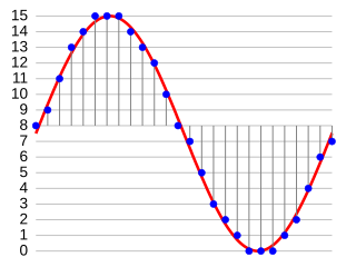
Pulse-code modulation (PCM) is a method used to digitally represent analog signals. It is the standard form of digital audio in computers, compact discs, digital telephony and other digital audio applications. In a PCM stream, the amplitude of the analog signal is sampled at uniform intervals, and each sample is quantized to the nearest value within a range of digital steps. Alec Reeves, Claude Shannon, Barney Oliver and John R. Pierce are credited with its invention.
