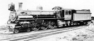
A steam locomotive is a locomotive that provides the force to move itself and other vehicles by means of the expansion of steam. It is fuelled by burning combustible material to heat water in the locomotive's boiler to the point where it becomes gaseous and its volume increases 1,700 times. Functionally, it is a steam engine on wheels.

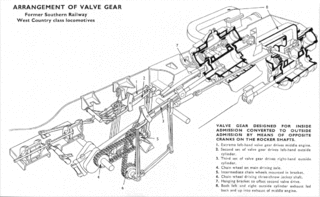
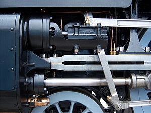
The valve gear of a steam engine is the mechanism that operates the inlet and exhaust valves to admit steam into the cylinder and allow exhaust steam to escape, respectively, at the correct points in the cycle. It can also serve as a reversing gear. It is sometimes referred to as the "motion".

The Walschaerts valve gear is a type of valve gear used to regulate the flow of steam to the pistons in steam locomotives, invented by Belgian railway engineer Egide Walschaerts in 1844. The gear is sometimes named without the final "s", since it was incorrectly patented under that name. It was extensively used in steam locomotives from the late 19th century until the end of the steam era.

In 1919, the Midland Railway built a single 0-10-0 steam locomotive, No 2290. It was designed by James Anderson for banking duties on the Lickey Incline in Worcestershire, England. It became known as "Big Bertha" or "Big Emma" by railwaymen and railway enthusiasts.

The GWR 4100 Class was a class of steam locomotives in the Great Western Railway (GWR) of the United Kingdom.
The Great Western Railway 3800 Class, also known as the County Class, were a class of 4-4-0 steam locomotives for express passenger train work introduced in 1904 in a batch of ten. Two more batches followed in 1906 and 1912 with minor differences. They were designed by George Jackson Churchward, who used standard components to produce a four-coupled version of his Saint Class 4-6-0s.

The Gresley conjugated valve gear is a valve gear for steam locomotives designed by Sir Nigel Gresley, chief mechanical engineer of the LNER, assisted by Harold Holcroft. It enables a three-cylinder locomotive to operate with only the two sets of valve gear for the outside cylinders, and derives the valve motion for the inside cylinder from them by means of levers. The gear is sometimes known as the Gresley-Holcroft gear, acknowledging Holcroft's major contributions to its development.

The Stephenson valve gear or Stephenson link or shifting link is a simple design of valve gear that was widely used throughout the world for various kinds of steam engines. It is named after Robert Stephenson but was invented by his employees.

Charles Benjamin Collett was Chief Mechanical Engineer of the Great Western Railway from 1922 to 1941. He designed the GWR's 4-6-0 Castle and King Class express passenger locomotives.
Edward Thompson was an English railway engineer, and was Chief Mechanical Engineer of the London and North Eastern Railway between 1941 and 1946. Edward Thompson was born at Marlborough, Wiltshire on 25 June 1881. He was the son of an assistant master at Marlborough College. He was educated at Marlborough before taking the Mechanical Science Tripos at Pembroke College, Cambridge, earning a third class degree. Thompson's academic background contrasts with that of his predecessor Nigel Gresley, who had also attended Marlborough, but then gained practical experience as a pupil at Horwich Works.
Henry Greenly (1876–1947) was amongst the foremost miniature railway engineers of the 20th century, remembered as a master of engineering design.

The SECR N1 class was a type of 3-cylinder 2-6-0 ('mogul') steam locomotive designed by Richard Maunsell for mixed traffic duties, initially on the South Eastern and Chatham Railway (SECR), and later operated for the Southern Railway (SR). The N1 was a development of the basic principles established by the Great Western Railway's (GWR) Chief Mechanical Engineer (CME) George Jackson Churchward and by Maunsell's previous N class design.

The Bulleid chain-driven valve gear is a type of steam locomotive valve gear designed by Oliver Bulleid during the Second World War for use on his Pacific (4-6-2) designs. It was peculiar to the Southern Railway in Britain, and borrowed from motor-vehicle practice in an attempt to create a compact and efficient design with a minimum of service requirements.

London and North Western Railway (LNWR) 2-2-2 No. 3020 Cornwall is a preserved steam locomotive. She was built as a 4-2-2 at Crewe Works in 1847, but was extensively rebuilt and converted into her current form in 1858.
A compound locomotive is a steam locomotive which is powered by a compound engine, a type of steam engine where steam is expanded in two or more stages. The locomotive was only one application of compounding. Two and three stages were used in ships, for example.
Lillian "Curly" Lawrence, known as LBSC, was one of Britain's most prolific and well known model or scale-steam-locomotive designers. LBSC were the initials of Britain's London, Brighton and South Coast Railway, where he was once employed as a fireman.

The South African Railways Class 10B 4-6-2 of 1910 was a steam locomotive from the pre-Union era in Transvaal.

A steam motor is a form of steam engine used for light locomotives and light self-propelled motor cars used on railways. The origins of steam motor cars for railways go back to at least the 1850s, if not earlier, as experimental economizations for railways or railroads with marginal budgets. These first examples, at least in North America, appear to have been fitted with light reciprocating engines, and either direct or geared drives, or geared-endless chain drives. Most incorporated a passenger carrying coach attached to the engine and its boiler. Boiler types varied in these earlier examples, with vertical boilers dominant in the first decade and then with very small diameter horizontal boilers. Other examples of steam motor cars incorporated an express-baggage or luggage type car body, with coupling apparatus provided to allow the steam motor car to draw a light passenger coach.

The Central South African Railways Rack 4-6-4RT of 1905 was a South African steam locomotive from the pre-Union era in Transvaal Colony.
GCR Class 9P was a design of four-cylinder steam locomotive of the 4-6-0 wheel arrangement built for hauling express passenger trains on the Great Central Railway in England. A total of six were built: one in 1917, and five in 1920. They were sometimes known as the Lord Faringdon class, from the name of the first one built.


