
An inductor, also called a coil, choke, or reactor, is a passive two-terminal electrical component that stores energy in a magnetic field when electric current flows through it. An inductor typically consists of an insulated wire wound into a coil.

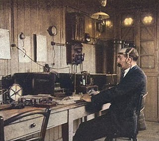
Wireless telegraphy or radiotelegraphy is transmission of text messages by radio waves, analogous to electrical telegraphy using cables. Before about 1910, the term wireless telegraphy was also used for other experimental technologies for transmitting telegraph signals without wires. In radiotelegraphy, information is transmitted by pulses of radio waves of two different lengths called "dots" and "dashes", which spell out text messages, usually in Morse code. In a manual system, the sending operator taps on a switch called a telegraph key which turns the transmitter on and off, producing the pulses of radio waves. At the receiver the pulses are audible in the receiver's speaker as beeps, which are translated back to text by an operator who knows Morse code.
In telecommunication, the free-space path loss (FSPL) is the attenuation of radio energy between the feedpoints of two antennas that results from the combination of the receiving antenna's capture area plus the obstacle-free, line-of-sight (LoS) path through free space. The "Standard Definitions of Terms for Antennas", IEEE Std 145-1993, defines "free-space loss" as "The loss between two isotropic radiators in free space, expressed as a power ratio." It does not include any power loss in the antennas themselves due to imperfections such as resistance. Free space loss increases with the square of distance between the antennas because the radio waves spread out by the inverse square law and decreases with the square of the wavelength of the radio waves. The FSPL is rarely used standalone, but rather as a part of the Friis transmission formula, which includes the gain of antennas. It is a factor that must be included in the power link budget of a radio communication system, to ensure that sufficient radio power reaches the receiver such that the transmitted signal is received intelligibly.

A Fresnel zone, named after physicist Augustin-Jean Fresnel, is one of a series of confocal prolate ellipsoidal regions of space between and around a transmitter and a receiver. The primary wave will travel in a relative straight line from the transmitter to the receiver. Aberrant transmitted radio, sound, or light waves which are transmitted at the same time can follow slightly different paths before reaching a receiver, especially if there are obstructions or deflecting objects between the two. The two waves can arrive at the receiver at slightly different times and the aberrant wave may arrive out of phase with the primary wave due to the different path lengths. Depending on the magnitude of the phase difference between the two waves, the waves can interfere constructively or destructively. The size of the calculated Fresnel zone at any particular distance from the transmitter and receiver can help to predict whether obstructions or discontinuities along the path will cause significant interference.
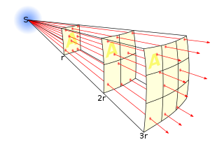
In science, an inverse-square law is any scientific law stating that a specified physical quantity is inversely proportional to the square of the distance from the source of that physical quantity. The fundamental cause for this can be understood as geometric dilution corresponding to point-source radiation into three-dimensional space.

A loading coil or load coil is an inductor that is inserted into an electronic circuit to increase its inductance. The term originated in the 19th century for inductors used to prevent signal distortion in long-distance telegraph transmission cables. The term is also used for inductors in radio antennas, or between the antenna and its feedline, to make an electrically short antenna resonant at its operating frequency.
The propagation constant of a sinusoidal electromagnetic wave is a measure of the change undergone by the amplitude and phase of the wave as it propagates in a given direction. The quantity being measured can be the voltage, the current in a circuit, or a field vector such as electric field strength or flux density. The propagation constant itself measures the change per unit length, but it is otherwise dimensionless. In the context of two-port networks and their cascades, propagation constant measures the change undergone by the source quantity as it propagates from one port to the next.

Line-of-sight propagation is a characteristic of electromagnetic radiation or acoustic wave propagation which means waves travel in a direct path from the source to the receiver. Electromagnetic transmission includes light emissions traveling in a straight line. The rays or waves may be diffracted, refracted, reflected, or absorbed by the atmosphere and obstructions with material and generally cannot travel over the horizon or behind obstacles.

In radio engineering, an antenna or aerial is the interface between radio waves propagating through space and electric currents moving in metal conductors, used with a transmitter or receiver. In transmission, a radio transmitter supplies an electric current to the antenna's terminals, and the antenna radiates the energy from the current as electromagnetic waves. In reception, an antenna intercepts some of the power of a radio wave in order to produce an electric current at its terminals, that is applied to a receiver to be amplified. Antennas are essential components of all radio equipment.

A parabolic antenna is an antenna that uses a parabolic reflector, a curved surface with the cross-sectional shape of a parabola, to direct the radio waves. The most common form is shaped like a dish and is popularly called a dish antenna or parabolic dish. The main advantage of a parabolic antenna is that it has high directivity. It functions similarly to a searchlight or flashlight reflector to direct radio waves in a narrow beam, or receive radio waves from one particular direction only. Parabolic antennas have some of the highest gains, meaning that they can produce the narrowest beamwidths, of any antenna type. In order to achieve narrow beamwidths, the parabolic reflector must be much larger than the wavelength of the radio waves used, so parabolic antennas are used in the high frequency part of the radio spectrum, at UHF and microwave (SHF) frequencies, at which the wavelengths are small enough that conveniently-sized reflectors can be used.

The near field and far field are regions of the electromagnetic (EM) field around an object, such as a transmitting antenna, or the result of radiation scattering off an object. Non-radiative near-field behaviors dominate close to the antenna or scattering object, while electromagnetic radiation far-field behaviors dominate at greater distances.

Effective radiated power (ERP), synonymous with equivalent radiated power, is an IEEE standardized definition of directional radio frequency (RF) power, such as that emitted by a radio transmitter. It is the total power in watts that would have to be radiated by a half-wave dipole antenna to give the same radiation intensity as the actual source antenna at a distant receiver located in the direction of the antenna's strongest beam. ERP measures the combination of the power emitted by the transmitter and the ability of the antenna to direct that power in a given direction. It is equal to the input power to the antenna multiplied by the gain of the antenna. It is used in electronics and telecommunications, particularly in broadcasting to quantify the apparent power of a broadcasting station experienced by listeners in its reception area.

Sir Edward Victor Appleton was an English physicist, Nobel Prize winner (1947) and pioneer in radiophysics. He studied, and was also employed as a lab technician, at Bradford College from 1909 to 1911.

In radio and telecommunications a dipole antenna or doublet is the simplest and most widely used class of antenna. The dipole is any one of a class of antennas producing a radiation pattern approximating that of an elementary electric dipole with a radiating structure supporting a line current so energized that the current has only one node at each end. A dipole antenna commonly consists of two identical conductive elements such as metal wires or rods. The driving current from the transmitter is applied, or for receiving antennas the output signal to the receiver is taken, between the two halves of the antenna. Each side of the feedline to the transmitter or receiver is connected to one of the conductors. This contrasts with a monopole antenna, which consists of a single rod or conductor with one side of the feedline connected to it, and the other side connected to some type of ground. A common example of a dipole is the "rabbit ears" television antenna found on broadcast television sets.

A spark-gap transmitter is an obsolete type of radio transmitter which generates radio waves by means of an electric spark. Spark-gap transmitters were the first type of radio transmitter, and were the main type used during the wireless telegraphy or "spark" era, the first three decades of radio, from 1887 to the end of World War I. German physicist Heinrich Hertz built the first experimental spark-gap transmitters in 1887, with which he proved the existence of radio waves and studied their properties.

In atmospheric, earth, and planetary sciences, a scale height, usually denoted by the capital letter H, is a distance over which a physical quantity decreases by a factor of e.
Antenna measurement techniques refers to the testing of antennas to ensure that the antenna meets specifications or simply to characterize it. Typical parameters of antennas are gain, bandwidth, radiation pattern, beamwidth, polarization, and impedance.
The invention of radio communication was preceded by many decades of establishing theoretical underpinnings, discovery and experimental investigation of radio waves, and engineering and technical developments related to their transmission and detection. These developments allowed Guglielmo Marconi to turn radio waves into a wireless communication system.
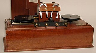
The magnetic detector or Marconi magnetic detector, sometimes called the "Maggie", was an early radio wave detector used in some of the first radio receivers to receive Morse code messages during the wireless telegraphy era around the turn of the 20th century. Developed in 1902 by radio pioneer Guglielmo Marconi from a method invented in 1895 by New Zealand physicist Ernest Rutherford it was used in Marconi wireless stations until around 1912, when it was superseded by vacuum tubes. It was widely used on ships because of its reliability and insensitivity to vibration. A magnetic detector was part of the wireless apparatus in the radio room of the RMS Titanic which was used to summon help during its famous 15 April 1912 sinking.
Barlow's law was an incorrect physical law proposed by Peter Barlow in 1825 to describe the ability of wires to conduct electricity. It said that the strength of the effect of electricity passing through a wire varies inversely with the square root of its length and directly with the square root of its cross-sectional area, or, in modern terminology:


