Reversing gear

Last updated
Steam reverser on a Southern Railway 2-8-0 Powerreverser.JPG
Steam reverser on a Southern Railway 2-8-0

On a steam locomotive, the reversing gear is used to control the direction of travel of the locomotive. It also adjusts the cutoff of the steam locomotive.

Contents

Reversing lever

This is the most common form of reverser. It is also known as a Johnson bar in the United States. It consists of a long lever mounted parallel to the direction of travel, on the driver’s side of the cab. It has a handle and sprung trigger at the top and is pivoted at the bottom to pass between two notched sector plates. The reversing rod, which connects to the valve gear, is attached to this lever, either above or below the pivot, in such a position as to give good leverage. A square pin is arranged to engage with the notches in the plates and hold the lever in the desired position when the trigger is released.

The advantages of this design are that change between forward and reverse gear can be made very quickly (as is needed in, for example, a shunting engine).

Limitations and drawbacks

The reversing lever has a catch mechanism which engages with a series of notches to hold the lever at the desired cut-off position. This means that the operator does not have a full choice of cut-off positions between maximum and mid-gear, but only those which correspond with the notches. The position of the notches is chosen by the locomotive designer or constructor with a view to the locomotive's intended purpose. In general engines designed for freight will have fewer notches with a 'longer' minimum cut-off (providing high tractive effort at low speeds but poor efficiency at high speeds) while a passenger locomotive will have more notches and a shorter minimum cut-off (allowing efficiency at high speeds at the expense of tractive effort). If the minimum cut-off provided for by the notches was too high, it would not be possible to run the locomotive in the efficient way described above (with a fully open regulator) without leading to steam wastage or 'choking' of the steam passages, so the regulator would have to be closed. That limits efficiency.

The Johnson Bar is effectively part of the entire valve gear, being connected to the various linkages and arms in order to serve its function in adjusting them. This means that the forces in the valve gear can be transmitted to the lever. This is especially the case if the engine has unbalanced slide valves, which have a high operating friction and are subject to steam forces on both sides of the valve. This friction meant that if the Johnson Bar is unlatched while the engine is operating under high steam pressure (wide regulator openings and high cut-off) or at high speeds, the forces that are supposed to act on the slide valves can instead be transmitted back through the linkage to the now-free reversing lever. This will suddenly and violently throw the lever into the full cut-off position, carrying with it the real danger of injury to the driver, damage to the valve gear and triggering wheel slip in the locomotive. The only way to prevent this is to close the regulator and allow the steam pressure in the valve chest to drop. The reversing lever can then be unlatched and set to a new cut-off position and then the regulator could be opened again. During this process the locomotive is not under power. On ascending gradients it was a matter of great skill to reduce the regulator opening by enough to safely unlatch the Johnson Bar while maintaining sufficient steam pressure to the cylinders. Each time the regulator was re-opened was a chance to encounter wheel slip and in loose coupled trains each closure and opening of the regulator set up dynamic forces throughout the length of the train which risked broken couplings. The screw reverser overcame all these issues.

Ban in the US

The dangers of the traditional Johnson Bar (which grew as locomotive power, weight and operating steam pressures increased through the first half of the 20th century) led to it being banned in the USA by the Interstate Commerce Commission. From 1939 all new-build steam locomotives had to be fitted with power reversers and from 1942 Johnson Bar-fitted engines undergoing heavy overhaul or rebuilding had to be retro-fitted with power reverse. Exceptions existed for light, low-powered locomotives and switchers. For switching, which required frequent changes of direction from full-ahead to full-reverse gear, the Johnson Bar was favored because the change could be made quickly in a single motion instead of the multiple turns of the handle of a low-geared screw reverser.

Screw reverser

Stephenson link valve gear.jpg
Diagram of Stephenson valve gear controlled by a screw reverser
Bulleid chain valve gear.gif
The two pistons of the steam reverser can be seen at the extreme left on this Bulleid Merchant Navy class

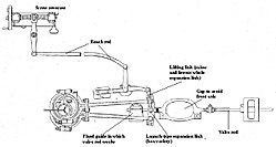
In the screw reverser mechanism (sometimes called a bacon slicer in the UK), the reversing rod is controlled by a screw and nut, worked by a wheel in the cab. The nut either operates on the reversing rod directly or through a lever, as above. The screw and nut may be cut with a double thread and a coarse pitch to move the mechanism as quickly as possible. The wheel is fitted with a locking lever to prevent creep and there is an indicator to show the percentage of cutoff in use. This method of altering the cutoff offers finer control than the sector lever, but it has the disadvantage of slow operation. It is most suitable for long-distance passenger engines where frequent changes of cutoff are not required and where fine adjustments offer the most benefit. On locomotives fitted with Westinghouse air brake equipment and Stephenson valve gear, it was common to use the screw housing as an air cylinder, with the nut extended to form a piston. Compressed air from the brake reservoirs was applied to one side of the piston to reduce the effort required to lift the heavy expansion link, with gravity assisting in the opposite direction. [1]

Power reverse gear

With larger engines, the linkages involved in controlling cutoff and direction grew progressively heavier and there was a need for power assistance in adjusting them. Steam (later, compressed air) powered reversing gears were developed in the late 19th and early 20th centuries. Typically, the operator worked a valve that admitted steam to one side or the other of a cylinder connected to the reversing mechanism until the indicator showed the intended position. A second mechanism—usually a piston in an oil-filled cylinder held in position by closing a control cock—was required to keep the linkages in place.

Stirling gear

The first locomotive engineer to fit such a device was James Stirling of the Glasgow and South Western Railway in 1873. [2] Several engineers then tried them, including William Dean of the GWR and Vincent Raven of the North Eastern Railway, but they found them little to their liking, mainly because of maintenance difficulties: any oil leakage from the locking cylinder, either through the piston gland or the cock, allowed the mechanism to creep, or worse “nose-dive”, into full forward gear while running. Stirling moved to the South Eastern Railway and Harry Smith Wainwright, his successor at that company, incorporated them into most of his designs, which were in production about thirty years after Stirling’s innovation. Later still the forward-looking Southern Railway engineer Oliver Bulleid fitted them to his famous Merchant Navy Class of locomotives, but they were mostly removed at rebuild.

Henszey's reversing gear

Patented in 1882, the Henszey's reversing gear illustrates a typical early solution. [3] Henszey's device consists of two pistons mounted on a single piston rod. Both pistons are double-ended. One is a steam piston to move the rod as required. The other, containing oil, holds the rod in a fixed position when the steam is turned off. Control is by a small three-way steam valve (“forward”, “stop”, “back”) and a separate indicator showing the position of the rod and thus the percentage of cutoff in use. When the steam valve is at “stop”, an oil cock connecting the two ends of the locking piston is also closed, thus holding the mechanism in position. The piston rod connects by levers to the reversing gear, which operates in the usual way, according to the type of valve gear in use.

The Ragonnet power reverser

The Ragonnet power reverse, patented in 1909, was a true feedback controlled servomechanism. The power reverse amplified small motions of the reversing lever made in the locomotive cab with modest force into much larger and more forceful motions of the reach rod that controlled the engine cutoff and direction. [4] It was usually air powered, but could also be steam powered. [5] The term servomotor was explicitly used by the developers of some later power reverse mechanisms. [6] The use of feedback control in these later power reverse mechanisms eliminated the need for a second cylinder for a hydraulic locking mechanism, and it restored the simplicity of a single operating lever that both controlled the reversing linkage and indicated its position.

Power reverse impetus

The development of articulated locomotives was a major impetus to the development of power reverse systems, because these typically had two or even three sets of reverse gear, instead of just one on a simple locomotive. [7] [8] The Baldwin Locomotive Works used the Ragonnet reversing gear, and other US builders generally abandoned positive locking features sooner than later. Many American locomotives were built, or retro-fitted, with power reversers, including the PRR K4s, PRR N1s, PRR B6, and PRR L1s, but in Britain locking cylinders remained in use. The Hadfield reversing gear, patented in 1950, was in most particulars a Ragonnet reversing gear with added locking cylinder. [9] Most Beyer Garratt locomotives used the Hadfield system. [10]

See also

Related Research Articles

<span class="mw-page-title-main">Steam engine</span> Heat engine that performs mechanical work using steam as its working fluid

A steam engine is a heat engine that performs mechanical work using steam as its working fluid. The steam engine uses the force produced by steam pressure to push a piston back and forth inside a cylinder. This pushing force can be transformed, by a connecting rod and crank, into rotational force for work. The term "steam engine" is generally applied only to reciprocating engines as just described, not to the steam turbine. Steam engines are external combustion engines, where the working fluid is separated from the combustion products. The ideal thermodynamic cycle used to analyze this process is called the Rankine cycle. In general usage, the term steam engine can refer to either complete steam plants, such as railway steam locomotives and portable engines, or may refer to the piston or turbine machinery alone, as in the beam engine and stationary steam engine.

Rail terminology is a form of technical terminology. The difference between the American term railroad and the international term railway is the most significant difference in rail terminology. These and other terms have often originated from the parallel development of rail transport systems in different parts of the world. In English-speaking countries outside the United Kingdom, a mixture of US and UK terms may exist.

<span class="mw-page-title-main">Valve gear</span> Mechanism for controlling steam flow in a reciprocating steam engine.

The valve gear of a steam engine is the mechanism that operates the inlet and exhaust valves to admit steam into the cylinder and allow exhaust steam to escape, respectively, at the correct points in the cycle. It can also serve as a reversing gear. It is sometimes referred to as the "motion".

<span class="mw-page-title-main">Steam locomotive components</span> Glossary of the main components of a typical steam locomotive

Main components found on a typical steam locomotive include:

<span class="mw-page-title-main">Walschaerts valve gear</span> Type of valve gear

The Walschaerts valve gear is a type of valve gear used to regulate the flow of steam to the pistons in steam locomotives, invented by Belgian railway engineer Egide Walschaerts in 1844. The gear is sometimes named without the final "s", since it was incorrectly patented under that name. It was extensively used in steam locomotives from the late 19th century until the end of the steam era.

<span class="mw-page-title-main">Automatic lubricator</span> Device fitted to a steam engine to supply lubricating oil

An automatic lubricator is a device fitted to a steam engine to supply lubricating oil to the cylinders and, sometimes, the bearings and axle box mountings as well. There are various types of automatic lubricator, which include various designs of displacement, hydrostatic and mechanical lubricators.

<span class="mw-page-title-main">Gresley conjugated valve gear</span> Type of mechanism for controlling steam flow in a reciprocating steam engine

The Gresley conjugated valve gear is a valve gear for steam locomotives designed by Sir Nigel Gresley, chief mechanical engineer of the LNER, assisted by Harold Holcroft. It enables a three-cylinder locomotive to operate with only the two sets of valve gear for the outside cylinders, and derives the valve motion for the inside cylinder from them by means of levers. The gear is sometimes known as the Gresley-Holcroft gear, acknowledging Holcroft's major contributions to its development.

<span class="mw-page-title-main">Stephenson valve gear</span> Simple design of valve gear

The Stephenson valve gear or Stephenson link or shifting link is a simple design of valve gear that was widely used throughout the world for various kinds of steam engines. It is named after Robert Stephenson but was invented by his employees.

In a steam engine, cutoff is the point in the piston stroke at which the inlet valve is closed. On a steam locomotive, the cutoff is controlled by the reversing gear.

<span class="mw-page-title-main">Corliss steam engine</span> Type of steam engine using rotary steam valves

A Corliss steam engine is a steam engine, fitted with rotary valves and with variable valve timing patented in 1849, invented by and named after the US engineer George Henry Corliss of Providence, Rhode Island.

<span class="mw-page-title-main">Piston valve (steam engine)</span> Form of valve within a steam engine or locomotive

Piston valves are one form of valve used to control the flow of steam within a steam engine or locomotive. They control the admission of steam into the cylinders and its subsequent exhausting, enabling a locomotive to move under its own power. The valve consists of two piston heads on a common spindle moving inside a steam chest, which is essentially a mini-cylinder located either above or below the main cylinders of the locomotive.

<span class="mw-page-title-main">Expansion valve (steam engine)</span>

An expansion valve is a device in steam engine valve gear that improves engine efficiency. It operates by closing off the supply of steam early, before the piston has travelled through its full stroke. This cut-off allows the steam to then expand within the cylinder. This expanding steam is still sufficient to drive the piston, even though its pressure decreases as it expands. As less steam is supplied in the shorter time for which the valve is open, use of the expansion valve reduces the steam consumed and thus the fuel required. The engine may deliver two-thirds of the work, for only one-third of the steam.

A steam brake is a type of brake for steam locomotives and their tenders, whereby a steam cylinder works directly on the brake linkages.

<span class="mw-page-title-main">Oscillating cylinder steam engine</span> Steam-engine design which does not require a valve gear

An oscillating cylinder steam engine is a simple steam-engine design that requires no valve gear. Instead the cylinder rocks, or oscillates, as the crank moves the piston, pivoting in the mounting trunnion so that ports in the cylinder line up with ports in a fixed port face alternately to direct steam into or out of the cylinder.

<span class="mw-page-title-main">Duplex locomotive</span> Type of steam locomotive

A duplex locomotive is a steam locomotive that divides the driving force on its wheels by using two pairs of cylinders rigidly mounted to a single locomotive frame; it is not an articulated locomotive. The concept was first used in France in 1863, but was particularly developed in the early 1930s by the Baldwin Locomotive Works, the largest commercial builder of steam locomotives in North America, under the supervision of its then chief engineer, Ralph P. Johnson.

<span class="mw-page-title-main">South African Class 10B 4-6-2</span>

The South African Railways Class 10B 4-6-2 of 1910 was a steam locomotive from the pre-Union era in Transvaal.

<span class="mw-page-title-main">Gab valve gear</span>

Gab valve gear was an early form of valve gear used on steam engines. Its simplest form allowed an engine to be stopped and started. A double form, mostly used on steam locomotives, allowed easy reversing.

<span class="mw-page-title-main">MÁV Class 601</span> Class of Hungarian Mallet-type locomotives

The MÁV class 601 is a class of Hungarian four cylinder Mallet -type locomotives, which was designed to haul long and very heavy cargo on very steep railway tracks. With their 22.5 meter length and 2200 KW power, they were the largest and most powerful steam locomotives which have ever built before the First World War in Europe.

<span class="mw-page-title-main">Cornish engine valve gear</span>

Valve gear opens and closes valves in the correct order. In rotating engines valve timings can be driven by eccentrics or cranks, but in non-rotative beam engines these options are not available. In the Cornish engine valves are driven either manually or through ‘plug rods’ and tappets driven from the beam. This permits the insertions of delays at various points in the cycle, allowing a Cornish Engine to vary from one stroke in ten minutes, to ten or more strokes in one minute, but also leads to some less familiar components when compared with rotative engines.

References

  1. "Railway Gazette :". Railway Gazette. Sutton, England. 86: 638. January 1946.
  2. Canestrari, Guido; Greggio, Luciano (1985). Steam Locomotives. Avenel, New Jersey: Crescent Books. p. 105. ISBN   0-517-48366-1.
  3. William P. Henszey, Reversing-Gear for Locomotives, U.S. Patent 259,538, June 13, 1882.
  4. Eugine L. Ragonnet, Controlling Mechanism for Locomotives, U.S. Patent 930,225, Aug. 9, 1909.
  5. Jacob H Yoder, Locomotive Valves and Valve Gears, , Van Nostrand, New York, 1917; page 131
  6. Lincoln A. Lang, Servo Motor Mechanism, U.S. Patent 1,480,940, Jan 15, 1924.
  7. George R. Henderson, Recent Locomotive Development, Paper 90,Transactions of the International Engineering Congress -- Railway Engineering, San Francisco, Sept. 20-25, 1915; page 491.
  8. Charles McShane, Locomotive Power Reverse Gears,The Locomotive Up to Date, Griffin & Winters, 1921; 413.
  9. James Hadfield, Hydraulic Locking Cylinder for Locomotive Reversing Gear, U.S. Patent 2,523,696, Sept. 26, 1950 (Oct. 7, 1944 in Great Britain).
  10. Ransome-Wallis, Patrick (2001). Illustrated Encyclopedia of World Railway Locomotives. Mineola, New York: Dover Books. p. 278. ISBN   0-486-41247-4.

Sources