Related Research Articles

Geotechnical engineering, also known as geotechnics, is the branch of civil engineering concerned with the engineering behavior of earth materials. It uses the principles and methods of soil mechanics and rock mechanics for the solution of engineering problems and the design of engineering works. It also relies on knowledge of geology, hydrology, geophysics, and other related sciences.
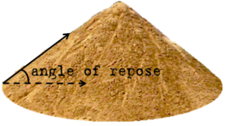
The angle of repose, or critical angle of repose, of a granular material is the steepest angle of descent or dip relative to the horizontal plane to which a material can be piled without slumping. At this angle, the material on the slope face is on the verge of sliding. The angle of repose can range from 0° to 90°. The morphology of the material affects the angle of repose; smooth, rounded sand grains cannot be piled as steeply as can rough, interlocking sands. The angle of repose can also be affected by additions of solvents. If a small amount of water is able to bridge the gaps between particles, electrostatic attraction of the water to mineral surfaces will increase the angle of repose, and related quantities such as the soil strength.

Soil mechanics is a branch of soil physics and applied mechanics that describes the behavior of soils. It differs from fluid mechanics and solid mechanics in the sense that soils consist of a heterogeneous mixture of fluids and particles but soil may also contain organic solids and other matter. Along with rock mechanics, soil mechanics provides the theoretical basis for analysis in geotechnical engineering, a subdiscipline of civil engineering, and engineering geology, a subdiscipline of geology. Soil mechanics is used to analyze the deformations of and flow of fluids within natural and man-made structures that are supported on or made of soil, or structures that are buried in soils. Example applications are building and bridge foundations, retaining walls, dams, and buried pipeline systems. Principles of soil mechanics are also used in related disciplines such as geophysical engineering, coastal engineering, agricultural engineering, hydrology and soil physics.
In construction or renovation, underpinning is the process of strengthening the foundation of an existing building or other structure. Underpinning may be necessary for a variety of reasons:

A falling weight deflectometer (FWD) is a testing device used by civil engineers to evaluate the physical properties of pavement in highways, local roads, airport pavements, harbor areas, railway tracks and elsewhere. The data acquired from FWDs is primarily used to estimate pavement structural capacity, to facilitate overlay design or determine if a pavement is being overloaded. Depending on its design, a FWD may be contained within a towable trailer or it may be built into a self-propelled vehicle such as a truck or van. Comprehensive road survey vehicles typically consist of a FWD mounted on a heavy truck together with a ground-penetrating radar and impact attenuator.

In geotechnical engineering, soil compaction is the process in which stress is applied to a soil causes densification as air is displaced from the pores between the soil grains. When stress is applied that causes densification due to water being displaced from between the soil grains, then consolidation, not compaction, has occurred. Normally, compaction is the result of heavy machinery compressing the soil, but it can also occur due to the passage of, for example, animal feet.
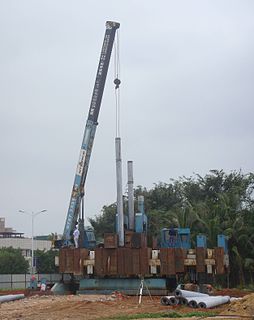
A pile driver is a device used to drive piles into soil to provide foundation support for buildings or other structures. The term is also used in reference to members of the construction crew that work with pile-driving rigs.

Geotechnical investigations are performed by geotechnical engineers or engineering geologists to obtain information on the physical properties of soil earthworks and foundations for proposed structures and for repair of distress to earthworks and structures caused by subsurface conditions. This type of investigation is called a site investigation. Additionally, geotechnical investigations are also used to measure the thermal resistivity of soils or backfill materials required for underground transmission lines, oil and gas pipelines, radioactive waste disposal, and solar thermal storage facilities. A geotechnical investigation will include surface exploration and subsurface exploration of a site. Sometimes, geophysical methods are used to obtain data about sites. Subsurface exploration usually involves soil sampling and laboratory tests of the soil samples retrieved.
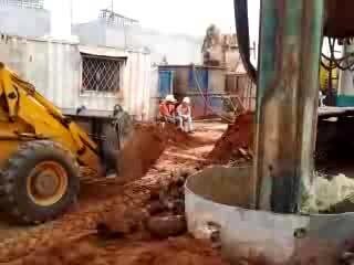
A deep foundation is a type of foundation that transfers building loads to the earth farther down from the surface than a shallow foundation does to a subsurface layer or a range of depths. A pile or piling is a vertical structural element of a deep foundation, driven or drilled deep into the ground at the building site.
A pile is a slender element cast in the ground or driven into it. Since pile construction as well as the final product are mostly invisible, engineers have often questioned their integrity, i.e. their compliance with project drawings and specifications. In fact, experience has shown that in piles, of all kinds flaws may occur. The purpose of integrity testing is to discover such flaws before they can cause any damage.
Crosshole sonic logging (CSL) is a method to the structural integrity of drilled shafts and other concrete piles.
Dynamic load testing is a method to assess a pile's bearing capacity by applying a dynamic load to the pile head while recording acceleration and strain on the pile head. Dynamic load testing is a high strain dynamic test which can be applied after pile installation for concrete piles. For steel or timber piles, dynamic load testing can be done during installation or after installation.
High strain dynamic testing is a method of testing deep foundations to obtain information about their capacity and integrity, and in some cases, to monitor their installation. It is codified by ASTM D4945-12 - Standard Test Method for High-Strain Dynamic Testing of Piles.
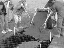
Cellular confinement systems (CCS)—also known as geocells—are widely used in construction for erosion control, soil stabilization on flat ground and steep slopes, channel protection, and structural reinforcement for load support and earth retention. Typical cellular confinement systems are geosynthetics made with ultrasonically welded high-density polyethylene (HDPE) strips or novel polymeric alloy (NPA)—and expanded on-site to form a honeycomb-like structure—and filled with sand, soil, rock, gravel or concrete.

Package testing or packaging testing involves the measurement of a characteristic or property involved with packaging. This includes packaging materials, packaging components, primary packages, shipping containers, and unit loads, as well as the associated processes.

Screw piles, sometimes referred to as screw anchors, screw-piles, helical piles, and helical anchors are a steel screw-in piling and ground anchoring system used for building deep foundations. Screw piles are manufactured using varying sizes of tubular hollow sections for the pile or anchors shaft.
A pipe support or pipe hanger is a designed element that transfer the load from a pipe to the supporting structures. The load includes the weight of the pipe proper, the content that the pipe carries, all the pipe fittings attached to pipe, and the pipe covering such as insulation. The four main functions of a pipe support are to anchor, guide, absorb shock, and support a specified load. Pipe supports used in high or low temperature applications may contain insulation materials. The overall design configuration of a pipe support assembly is dependent on the loading and operating conditions.
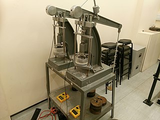
An oedometer test is a kind of geotechnical investigation performed in geotechnical engineering that measures a soil's consolidation properties. Oedometer tests are performed by applying different loads to a soil sample and measuring the deformation response. The results from these tests are used to predict how a soil in the field will deform in response to a change in effective stress.
Static load testing is an in situ type of load testing used in geotechnical investigation to determine the bearing capacity of deep foundations prior to the construction of a building. It differs from the statnamic load test and dynamic load testing in that the pressure applied to the pile is slower. Static load testings are performed in order to measure a design’s axial tension or axial compression. It can also be used to measure its deflected shape under lateral load

Offshore embedded anchors are anchors that derive their holding capacity from the frictional, or bearing, resistance of the surrounding soil, as opposed to gravity anchors, which derive their holding capacity largely from their weight. As offshore developments move into deeper waters, gravity-based structures become less economical due to the large size needed and the consequent cost of transportation.
References
- 1 2 3 4 Middendorp, P. (2000) Statnamic the engineering of art. Proc.6th Int. Conf. on the Application of Stress Wave Theory to Piles, Balkema, Rotterdam, 551–562
- 1 2 Middendorp, P., Bermingham, P. & Kuiper, B. (1992) Statnamic load testing of foundation piles. 4th Int. Conf. on the Application of Stresswave Theory to Piles, The Hague 21–24 September 1992, pp. 265–272
- ↑ "ASTM D7383 - 08 Standard Test Methods for Axial Compressive Force Pulse (Rapid) Testing of Deep Foundations". ASTM International - Standards Worldwide. Retrieved 2020-11-13.
- Brown M.J. & Powell, J.J.M (2013) Comparison of rapid load test analysis techniques in clay soils. ASCE Journal of Geotechnical & Geoenvironmental Engineering. Vol 139, No. 1, pp. 152–161.
- Hoelscher, HÖLSCHER, P. BRASSINGA, H., BROWN, M.J. MIDDENDORP, P. & PROFITTLICH, M. & van TOL, F.A (2011) Rapid Load Testing on Piles Interpretation Guidelines. CRC Press/Balkema, Leiden, Netherlands.
- Brown, M.J., Hyde, A.F.L. & Anderson, W.F. (2006) Analysis of a rapid load test on an instrumented bored pile in clay. Geotechnique. Vol. 56, No. 9. pp. 627-638.
- Brown, M.J. & Hyde, A.F.L. (2006) Some observations of Statnamic pile testing. Proc. Inst. of Civil Engineers: Geotechnical Engineering Journal, Vol 159, GE4. pp. 269-273.
- Brown, D.A. (1994) Evaluation of static capacity of deep foundations from Statnamic testing. Geotech. Testing J., ASTM, 17(4), 403-414.