Method used to determine the geotechnical engineering properties of soils
A CPT truck operated by the USGS.Symbol used in drawingsSimplified version of a cone penetrometer.
The cone penetration or cone penetrometer test (CPT) is a method used to determine the geotechnical engineering properties of soils and delineating soil stratigraphy. It was initially developed in the 1950s at the Dutch Laboratory for Soil Mechanics in Delft to investigate soft soils. Based on this history it has also been called the "Dutch cone test". Today, the CPT is one of the most used and accepted soil methods for soil investigation worldwide.
The test method consists of pushing an instrumented cone, with the tip facing down, into the ground at a controlled rate (controlled between 1.5 -2.5cm/s accepted). The resolution of the CPT in delineating stratigraphic layers is related to the size of the cone tip, with typical cone tips having a cross-sectional area of either 10 or 15cm2, corresponding to diameters of 3.6 and 4.4cm. A very early ultra-miniature 1cm2 subtraction penetrometer was developed and used on a US mobile ballistic missile launch system (MGM-134 Midgetman) soil/structure design program in 1984 at the Earth Technology Corporation of Long Beach, California.
History and development
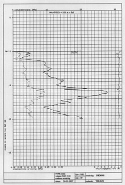
The result of a cone penetration test: resistance and friction on the left, friction ratio (%) on the right.
The early applications of CPT mainly determined the logistics of soil geotechnical property of bearing capacity. The original cone penetrometers involved simple mechanical measurements of the total penetration resistance to pushing a tool with a conical tip into the soil. Different methods were employed to separate the total measured resistance into components generated by the conical tip (the "tip friction") and friction generated by the rod string. A friction sleeve was added to quantify this component of the friction and aid in determining soil cohesive strength in the 1960s.[1] Electronic measurements began in 1948 and improved further in the early 1970s.[2] Most modern electronic CPT cones now also employ a pressure transducer with a filter to gather pore water pressure data. The filter is usually located either on the cone tip (the so-called U1 position), immediately behind the cone tip (the most common U2 position) or behind the friction sleeve (U3 position). Pore water pressure data aids determining stratigraphy and is primarily used to correct tip friction values for those effects. CPT testing which also gathers this piezometer data is called CPTU testing. CPT and CPTU testing equipment generally advances the cone using hydraulic rams mounted on either a heavily ballasted vehicle or using screwed-in anchors as a counter-force. One advantage of CPT over the Standard Penetration Test (SPT) is a more continuous profile of soil parameters, with data recorded at intervals typically of 2cm but as small as 1cm.
Manufacturers of cone penetrometer probes and data acquisition systems include Hogentogler, which has been acquired by the Vertek Division of Applied Research Associates,[3][4] GeoPoint Systems BV[5] and Pagani Geotechnical Equipment.[6]
Additional in situ testing parameters
In addition to the mechanical and electronic cones, a variety of other CPT-deployed tools have been developed over the years to provide additional subsurface information. One common tool advanced during CPT testing is a geophone set to gather seismic shear wave and compression wave velocities. This data helps determine the shear modulus and Poisson's ratio at intervals through the soil column for soil liquefaction analysis and low-strain soil strength analysis. Engineers use the shear wave velocity and shear modulus to determine the soil's behavior under low-strain and vibratory loads. Additional tools such as laser-induced fluorescence, X-ray fluorescence,[7] soil conductivity/resistivity,[8]pH, temperature and membrane interface probe and cameras for capturing video imagery are also increasingly advanced in conjunction with the CPT probe.
An additional CPT deployed tool used in Britain, Netherlands, Germany, Belgium and France is a piezocone combined with a tri-axial magnetometer. This is used to attempt to ensure that tests, boreholes, and piles, do not encounter unexploded ordnance (UXO) or duds. The magnetometer in the cone detects ferrous materials of 50kg or larger within a radius of up to about 2m distance from the probe depending on the material, orientation and soil conditions.
Standards and use
CPT for geotechnical applications was standardized in 1986 by ASTM Standard D 3441 (ASTM, 2004). ISSMGE provides international standards on CPT and CPTU. Later ASTM Standards have addressed the use of CPT for various environmental site characterization and groundwater monitoring activities.[9][10][11] For geotechnical soil investigations, CPT is more popular compared to SPT as a method of geotechnical soil investigation. Its increased accuracy, speed of deployment, more continuous soil profile and reduced cost over other soil testing methods. The ability to advance additional in situ testing tools using the CPT direct push drilling rig, including the seismic tools described above, are accelerating this process.
References
↑Begemann, H. K. S, 1965, "The Friction Jacket Cone as an Aid in Determining the Soil Profile"; Proceedings, 6th ICSMFE, Montreal, Quebec, Canada, Vol I, pp.17-20.
↑De Reister, J., 1971, "Electric Penetrometer for Site Investigations"; Journal of SMFE Division, ASCE, Vol. 97, SM-2, pp. 457-472.
↑"Home". chemistry.nrl.navy.mil. Archived from the original on 2007-08-21. Retrieved 2015-04-20.
↑Strutynsky, A.I., R. Sandiford, D. Cavaliere, 1991. Use of Piezometric Cone Penetration Testing with Electrical Conductivity Measurements (CPTU-EC) for Detection of Hydrocarbon Contamination in Saturated Granular Soils. Current Practices in Ground Water and Vadose Zone Investigations, ASTM
↑Strutynsky, A.I., T. Sainey, 1990. Use of the Piezometric Cone Penetration Test and Penetrometer Groundwater Sampling for Volatile Organic Contaminant Plume Detection. Petroleum Hydrocarbons and Organic Chemicals in Groundwater: Prevention, Detection and Restoration. API/NWWA
ASTM, 2004, "Standard Method of Deep Quasi-Static Cone and Friction-Cone Penetration Tests of Soil"; ASTM Standard D 3441, ASTM International, West Conshohocken, PA, 7 pp.
ASTM D-5778 "Standard Test Method for Performing Electronic Friction Cone and Piezocone Penetration Testing of Soils".
International Reference Test Procedure for CPT and CPTU - International Society of Soil Mechanics and Geotechnical Engineering (ISSMGE)
Mayne, Paul; Auxt, Jay A.; Mitchell, James K.; Yilmaz, Recep (October 4–5, 1995). "U.S. National Report on CPT"(PDF). Proceedings, International Symposium on Cone Penetration Testing, Vol. 1 (CPT '95). Linköping, Sweden: Swedish Geotechnical Society. pp.263–276. Retrieved 2011-09-26.
This page is based on this Wikipedia article Text is available under the CC BY-SA 4.0 license; additional terms may apply. Images, videos and audio are available under their respective licenses.