Many variations of aircraft engine starting have been used since the Wright brothers made their first powered flight in 1903. The methods used have been designed for weight saving, simplicity of operation and reliability. Early piston engines were started by hand. Geared hand starting, electrical and cartridge-operated systems for larger engines were developed between the First and Second World Wars.
Gas turbine aircraft engines such as turbojets, turboshafts and turbofans often use air/pneumatic starting, with the use of bleed air from built-in auxiliary power units (APUs) or external air compressors now seen as a common starting method. Often only one engine needs be started using the APU (or remote compressor). After the first engine is started using APU bleed air, cross-bleed air from the running engine can be used to start the remaining engine(s).
Piston engines
Hand starting/propeller swinging
A 1918 sketch of ground crew receiving instruction on hand starting
Hand starting of aircraft piston engines by swinging the propeller is the oldest and simplest method, the absence of any onboard starting system giving an appreciable weight saving. Positioning of the propeller relative to the crankshaft is arranged such that the engine pistons pass through top dead centre during the swinging stroke.
As the ignition system is normally arranged to produce sparks before top dead centre there is a risk of the engine kicking back during hand starting. To avoid this problem one of the two magnetos used in a typical aero engine ignition system is fitted with an 'impulse coupling', a spring-loaded device which delays the spark until top dead centre and which also increases the rotational speed of the magneto to produce a stronger spark. When the engine fires, the impulse coupling no longer operates and the second magneto is switched on.[1] As aero engines grew bigger in capacity (during the interwar period), single-person propeller swinging became physically difficult—ground crew personnel would either join hands and pull together as a team, or else a canvas sock would be fitted over one propeller blade, the sock having a length of rope attached to the propeller tip end.[2][3] Note that this is different from the manual "turning over" of a radial piston engine, which is done to release oil that has become trapped in the lower cylinders prior to starting to avoid engine damage. The two appear similar, but while hand starting involves a sharp, strong "yank" on the prop to start the engine, turning over is simply done by turning the prop through a certain set amount.
Accidents have occurred during lone pilot hand starting, whether due to high throttle settings, brakes not having been applied, or wheel chocks not being used, all resulting in the aircraft moving off without the pilot at the controls.[4] "Turning the engine" with the ignition and switches accidentally being left "on" can also cause injury if the engine starts unexpectedly when a spark plug fires—if the switch is not in the "start" position, the spark will occur before the piston hits top dead center, which can force the propeller to violently kick back.
The Hucks starter (invented by Bentfield Hucks during WWI) is a mechanical replacement for the ground crew. Based on a vehicle chassis the device uses a clutch driven shaft to turn the propeller, disengaging as the engine starts. A Hucks starter is used regularly at the Shuttleworth Collection for starting period aircraft.[3]
Self-sustaining motor gliders (often known as 'turbos') are fitted with small two-stroke engines with no starting system, for ground testing a cord is wrapped around the propeller boss and pulled rapidly in conjunction with operating decompressor valves. These engines are started in flight by operating the decompressor and increasing airspeed to windmill the propeller. Early variants of the Slingsby Falke motor glider use a cockpit mounted pull start system.[5]
Aircraft began to be equipped with electrical systems around 1930, powered by a battery and small wind-driven generator. The systems were initially not powerful enough to drive starter motors. Introduction of engine-driven generators solved the problem.[6]
Introduction of electric starter motors for aero engines increased convenience at the expense of extra weight and complexity. They were a necessity for flying boats with high mounted, inaccessible engines. Powered by an onboard battery, ground electrical supply or both, the starter is operated by a key or switch in the cockpit. The key system usually facilitates switching of the magnetos.[6][7]
In cold ambient conditions the friction caused by viscous engine oil causes a high load on the starting system. Another problem is the reluctance of the fuel to vaporise and combust at low temperatures. Oil dilution systems were developed (mixing fuel with the engine oil),[8] and engine pre-heaters were used (including lighting fires under the engine). The Ki-Gass priming pump system was used to assist starting of British engines.[9]
Many light aircraft are fitted with a 'starter engaged' warning light in the cockpit, a mandatory airworthiness requirement to guard against the risk of the starter motor failing to disengage from the engine.[10]
The Coffman starter was an explosive cartridge operated device, the burning gases either operating directly in the cylinders to rotate the engine or operating through a geared drive. First introduced on the Junkers Jumo 205 diesel engine in 1936 the Coffman starter was not widely used by civil operators due to the expense of the cartridges.[11]
Pneumatic starter
In 1920 Roy Fedden designed a piston engine gas starting system, used on the Bristol Jupiter engine in 1922.[3] A system used in early Rolls-Royce Kestrel engines ducted high-pressure air from a ground unit through a camshaft driven distributor to the cylinders via non-return valves, the system had disadvantages only overcome by conversion to electric starting.[12]
In-flight starting
When a piston engine needs to be started in flight the electric starter motor can be used. This is a normal procedure for motor gliders that have been soaring with the engine turned off. During aerobatics with earlier aircraft types it was not uncommon for the engine to cut during manoeuvres due to carburettor design. With no electric starter installed, engines can be restarted by diving the aircraft to increase airspeed and the rotation speed of the 'windmilling' propeller.[13]
Inertia starter
An aero engine inertia starter uses a pre-rotated flywheel to transfer kinetic energy to the crankshaft, normally through reduction gears and a clutch to prevent over-torque conditions. Three variations have been used, hand driven, electrically driven and a combination of both. When the flywheel is fully energised either a manual cable is pulled or a solenoid is used to engage the starter.[14]
Gas turbine engines
Starting of a gas turbine engine requires rotation of the compressor to a speed that provides sufficient pressurised air to the combustion chambers. The starting system has to overcome inertia of the compressor and friction loads, the system remains in operation after combustion starts and is disengaged once the engine has reached self-idling speed.[15][16]
Two types of electrical starter motor can be used, direct-cranking (to disengage as internal combustion engines) and starter-generator system (permanently engaged).[17]
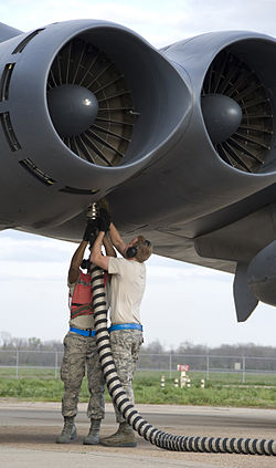
With air-start systems, gas turbine engine compressor spools are rotated by the action of a large volume of compressed air acting directly on the compressor blades or driving the engine through a small, geared turbine motor. These motors can weigh up to 75% less than an equivalent electrical system.[15]
The compressed air can be supplied from an on-board auxiliary power unit (APU), a portable gas generator used by ground crew or by cross feeding bleed air from a running engine in the case of multi-engined aircraft.[19]
Versions of the Rolls-Royce Avon turbojet engine used a geared turbine starter motor that burned isopropyl nitrate as the fuel. In military service this monofuel had the NATO designation of S-746 AVPIN. For starting a measured amount of fuel was introduced to the starter combustion chamber then ignited electrically, the hot gases spinning the turbine at high revolutions with the exhaust exiting overboard.[21]
Similar in operating principle to the piston engine Coffman starter, an explosive cartridge drives a small turbine engine which is connected by gears to the compressor shaft.[22]
Developed for short-haul airliners, most civil and military aircraft requiring self-contained starting systems these units are known by various names including Auxiliary Power Unit (APU), Jet Fuel Starter (JFS), Air Start Unit (ASU) or Gas Turbine Compressor (GTC).[21] Comprising a small gas turbine which is electrically started, these devices provide compressed bleed air for engine starting and often also provide electrical and hydraulic power for ground operations without the need to run the main engines.[23] ASUs are used today within the civil and military Ground Support to serve Aircraft on main engine start (MES) and pneumatic bleed-air-support for the Environmental Control System (ECS) cooling and heating
Internal combustion engine starter
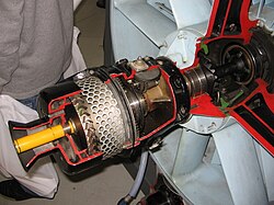
Riedel two-stroke starter motor of the Junkers Jumo 004. Note the pull-cord handle
An interesting feature of all three German jet engine designs that saw production of any kind before May 1945 (the German BMW 003, Junkers Jumo 004 and Heinkel HeS 011 axial-flow turbojet engine designs) was the starter system, which consisted of a Riedel 10hp (7.5kW) flat twintwo-stroke air-cooled engine hidden in the intake, and essentially functioned as a pioneering example of an auxiliary power unit (APU) for starting a jet engine — for the Jumo 004, a hole in the extreme nose of the intake diverter contained a D-shaped manual pull-cord handle which started the piston engine, which in turn rotated the compressor.[24] Two small petrol/oil mix tanks were fitted in the annular intake.[25]
Sufficient airspeed is used to 'windmill' the compressor then fuel and ignition are switched on, an on-board auxiliary power unit may be used at high altitudes where the air density is lower.[16]
During zoom climb operations of the Lockheed NF-104A the jet engine was shut down on climbing through 85,000ft (26,000m) and was started using the windmill method on descent through denser air.[26]
Pulse jet engines are uncommon aircraft powerplants. However, the Argus As 014 used to power the V-1 flying bomb and Fieseler Fi 103R Reichenberg was a notable exception. In this pulse jet three air nozzles in the front section were connected to an external high-pressure air source, butane from an external supply was used for starting, ignition was accomplished by a spark plug located behind the shutter system, electricity to the plug being supplied from a portable starting unit.[27]
Once the engine started and the temperature rose to the minimum operating level, the external air hose and connectors were removed, and the resonant design of the tailpipe kept the pulse jet firing. Each cycle or pulse of the engine began with the shutters open; fuel was injected behind them and ignited, and the resulting expansion of gases forced the shutters closed. As the pressure in the engine dropped following combustion, the shutters reopened and the cycle was repeated, roughly 40 to 45 times per second. The electrical ignition system was used only to start the engine; heating of the tailpipe skin maintained combustion.[27]
This page is based on this Wikipedia article Text is available under the CC BY-SA 4.0 license; additional terms may apply. Images, videos and audio are available under their respective licenses.