Token ring

Last updated
Two examples of Token Ring networks: a) Using a single MAU b) Using several MAUs connected to each other Token ring.svg
Two examples of Token Ring networks: a) Using a single MAU b) Using several MAUs connected to each other
Token Ring network TokenRingLogicalNetwork.svg
Token Ring network
Token Ring network: operation of a MAU explained Physical Token Ring Wiring.jpg
Token Ring network: operation of a MAU explained
IBM hermaphroditic connector with locking clip IBM hermaphroditic connector.JPG
IBM hermaphroditic connector with locking clip

Token Ring is a computer networking technology used to build local area networks. It uses a special three-byte frame called a token that travels around a logical ring of workstations or servers. This token passing is a channel access method providing fair access for all stations, and eliminating the collisions of contention-based access methods.

Contents

There were several other earlier implementations of token-passing networks. [ clarification needed ]

Token Ring was introduced by IBM in 1984, and standardized in 1989 as IEEE 802.5. It was a successful technology, particularly in corporate environments, but was gradually eclipsed by the later versions of Ethernet.

History

A wide range of different local area network technologies were developed in the early 1970s, of which one, the Cambridge Ring, had demonstrated the potential of a token passing ring topology, and many teams worldwide began working on their own implementations. At the IBM Zurich Research Laboratory Werner Bux and Hans Müller, in particular, worked on the design and development of IBM's Token Ring technology, [1] while early work at MIT [2] led to the Proteon 10 Mbit/s ProNet-10 Token Ring network in 1981 the same year that workstation vendor Apollo Computer introduced their proprietary 12 Mbit/s Apollo Token Ring (ATR) network running over 75-ohm RG-6U coaxial cabling. [3] Proteon later evolved a 16 Mbit/s version that ran on unshielded twisted pair cable.

IBM launched their own proprietary Token Ring product on October 15, 1985. [4] It ran at 4  Mbit/s, and attachment was possible from IBM PCs, midrange computers and mainframes. It used a convenient star-wired physical topology and ran over shielded twisted-pair cabling. Shortly thereafter it became the basis for the (ANSI)/IEEE standard 802.5. [5]

During this time, IBM argued strongly that Token Ring LANs were superior to Ethernet, especially under load, [6] but these claims were fiercely debated. [7]

In 1988 the faster 16 Mbit/s Token Ring was standardized by the 802.5 working group, [8] and an increase to 100 Mbit/s was standardized and marketed during the wane of Token Ring's existence. However it was never widely used, [9] and while a 1000 Mbit/s standard was approved in 2001, no products were ever brought to market [10] and standards activity came to a standstill as Fast Ethernet and Gigabit Ethernet dominated the local area networking market.

Comparison with Ethernet

Ethernet and Token Ring have some notable differences:

Operation

Stations on a Token Ring LAN are logically organized in a ring topology with data being transmitted sequentially from one ring station to the next with a control token circulating around the ring controlling access. Similar token passing mechanisms are used by ARCNET, token bus, 100VG-AnyLAN (802.12) and FDDI, and they have theoretical advantages over the CSMA/CD of early Ethernet. [15]

A Token Ring network can be modeled as a polling system where a single server provides service to queues in a cyclic order. [16]

Access control

The data transmission process goes as follows:

Multistation Access Units and Controlled Access Units

The IBM 8228 Multistation Access Unit with accompanying Setup Aid to prime the relays on each port IBM 8228 Multistation Access Unit.JPG
The IBM 8228 Multistation Access Unit with accompanying Setup Aid to prime the relays on each port

Physically, a Token Ring network is wired as a star, with 'MAUs' in the center, 'arms' out to each station, and the loop going out-and-back through each. [17]

A MAU could present in the form of a hub or a switch; since Token Ring had no collisions many MAUs were manufactured as hubs. Although Token Ring runs on LLC, it includes source routing to forward packets beyond the local network. The majority of MAUs are configured in a 'concentration' configuration by default, but later MAUs also supporting a feature to act as splitters and not concentrators exclusively such as on the IBM 8226. [18]

Token ring concentrator diagram.png

Later IBM would release Controlled Access Units that could support multiple MAU modules known as a Lobe Attachment Module. The CAUs supported features such as Dual-Ring Redundancy for alternate routing in the event of a dead port, modular concentration with LAMs, and multiple interfaces like most later MAUs. [19] This offered a more reliable setup and remote management than with an unmanaged MAU hub.

Cabling and interfaces

Cabling is generally IBM "Type-1", a heavy two-pair 150 Ohm shielded twisted pair cable. This was the basic cable for the "IBM Cabling System", a structured cabling system that IBM hoped would be widely adopted. Unique hermaphroditic connectors, commonly referred to as IBM Data Connectors in formal writing or colloquially as Boy George connectors were used. [20] The connectors have the disadvantage of being quite bulky, requiring at least 3 x 3 cm panel space, and being relatively fragile. The advantages of the connectors being that they are genderless and have superior shielding over standard unshielded 8P8C. Connectors at the computer were usually DE-9 female.

In later implementations of Token Ring, Cat 4 cabling was also supported, so 8P8C ("RJ45") connectors were used on both of the MAUs, CAUs and NICs; with many of the network cards supporting both 8P8C and DE-9 for backwards compatibility. [17]

Technical details

Frame types

Token

When no station is sending a frame, a special token frame circles the loop. This special token frame is repeated from station to station until arriving at a station that needs to send data.

Tokens are 3 bytes in length and consist of a start delimiter, an access control byte, and an end delimiter.

Start DelimiterAccess ControlEnd Delimiter
8-bits8-bits8-bits

Abort frame

Used to abort transmission by the sending station

SDED
8 bits8 bits

Data

Data frames carry information for upper-layer protocols, while command frames contain control information and have no data for upper-layer protocols. Data/command frames vary in size, depending on the size of the Information field.

SDACFCDASAPDU from LLC (IEEE 802.2)CRCEDFS
8 bits8 bits8 bits48 bits48 bitsup to 4500x8 bits32 bits8 bits8 bits
Starting delimiter
Consists of a special bit pattern denoting the beginning of the frame. The bits from most significant to least significant are J,K,0,J,K,0,0,0. J and K are code violations. Since Manchester encoding is self-clocking, and has a transition for every encoded bit 0 or 1, the J and K codings violate this, and will be detected by the hardware. Both the Starting Delimiter and Ending Delimiter fields are used to mark frame boundaries.
JK0JK000
1 bit1 bit1 bit1 bit1 bit1 bit1 bit1 bit
Access control
This byte field consists of the following bits from most significant to least significant bit order: P,P,P,T,M,R,R,R. The P bits are priority bits, T is the token bit which when set specifies that this is a token frame, M is the monitor bit which is set by the Active Monitor (AM) station when it sees this frame, and R bits are reserved bits.
+Bits 0–2345–7
0PriorityTokenMonitorReservation
Frame control
A one-byte field that contains bits describing the data portion of the frame contents which indicates whether the frame contains data or control information. In control frames, this byte specifies the type of control information.
+Bits 0–1Bits 2–7
0Frame typeControl Bits

Frame type – 01 indicates LLC frame IEEE 802.2 (data) and ignore control bits; 00 indicates MAC frame and control bits indicate the type of MAC control frame

Destination address
A six-byte field used to specify the destination(s) physical address.
Source address
Contains physical address of sending station. It is a six-byte field that is either the local assigned address (LAA) or universally assigned address (UAA) of the sending station adapter.
Data
A variable length field of 0 or more bytes, the maximum allowable size depending on ring speed containing MAC management data or upper layer information. Maximum length of 4500 bytes.
Frame check sequence
A four-byte field used to store the calculation of a CRC for frame integrity verification by the receiver.
Ending delimiter
The counterpart to the starting delimiter, this field marks the end of the frame and consists of the following bits from most significant to least significant: J,K,1,J,K,1,I,E. I is the intermediate frame bit and E is the error bit.
JK1JK1IE
11 bit1 bit1 bit1 bit1 bit1 bit1 bit
Frame status
A one-byte field used as a primitive acknowledgment scheme on whether the frame was recognized and copied by its intended receiver.
AC00AC00
1 bit1 bit1 bit1 bit1 bit1 bit1 bit1 bit

A = 1, Address recognized C = 1, Frame copied

Active and standby monitors

Every station in a Token Ring network is either an active monitor (AM) or standby monitor (SM) station. There can be only one active monitor on a ring at a time. The active monitor is chosen through an election or monitor contention process.

The monitor contention process is initiated when the following happens:

When any of the above conditions take place and a station decides that a new monitor is needed, it will transmit a "claim token" frame, announcing that it wants to become the new monitor. If that token returns to the sender, it is OK for it to become the monitor. If some other station tries to become the monitor at the same time then the station with the highest MAC address will win the election process. Every other station becomes a standby monitor. All stations must be capable of becoming an active monitor station if necessary.

The active monitor performs a number of ring administration functions. The first function is to operate as the master clock for the ring in order to provide synchronization of the signal for stations on the wire. Another function of the AM is to insert a 24-bit delay into the ring, to ensure that there is always sufficient buffering in the ring for the token to circulate. A third function for the AM is to ensure that exactly one token circulates whenever there is no frame being transmitted, and to detect a broken ring. Lastly, the AM is responsible for removing circulating frames from the ring.

Token insertion process

Token Ring stations must go through a 5-phase ring insertion process before being allowed to participate in the ring network. If any of these phases fail, the Token Ring station will not insert into the ring and the Token Ring driver may report an error.

Optional priority scheme

In some applications there is an advantage to being able to designate one station having a higher priority. Token Ring specifies an optional scheme of this sort, as does the CAN Bus, (widely used in automotive applications) - but Ethernet does not.

In the Token Ring priority MAC, eight priority levels, 0–7, are used. When the station wishing to transmit receives a token or data frame with a priority less than or equal to the station's requested priority, it sets the priority bits to its desired priority. The station does not immediately transmit; the token circulates around the medium until it returns to the station. Upon sending and receiving its own data frame, the station downgrades the token priority back to the original priority.

Here are the following eight access priority and traffic types for devices that support 802.1Q and 802.1p:

Priority bitsTraffic type
x'000'Normal data traffic
x'001'Not used
x'010'Not used
x'011'Not used
x'100'Normal data traffic (forwarded from other devices)
x'101'Data sent with time sensitivity requirements
x'110'Data with real time sensitivity (i.e. VoIP)
x'111'Station management

Bridging Token Ring and Ethernet

Both Token Ring and Ethernet interfaces on the 2210-24M IBM 2210 Router Interfaces.JPG
Both Token Ring and Ethernet interfaces on the 2210-24M

Bridging solutions for Token Ring and Ethernet networks included the AT&T StarWAN 10:4 Bridge, the IBM 9208 LAN Bridge and the Microcom LAN Bridge. [21] Alternative connection solutions incorporated a router that could be configured to dynamically filter traffic, protocols and interfaces, such as the IBM 2210-24M Multiprotocol Router which contained both Ethernet and Token Ring interfaces. [22]

See also

Related Research Articles

Ethernet Computer networking technology

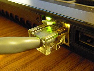
Ethernet is a family of computer networking technologies commonly used in local area networks (LAN), metropolitan area networks (MAN) and wide area networks (WAN). It was commercially introduced in 1980 and first standardized in 1983 as IEEE 802.3. Ethernet has since been refined to support higher bit rates, a greater number of nodes, and longer link distances, but retains much backward compatibility. Over time, Ethernet has largely replaced competing wired LAN technologies such as Token Ring, FDDI and ARCNET.

IEEE 802.11 Specifications for Wi-FI wireless networks

IEEE 802.11 is part of the IEEE 802 set of local area network (LAN) protocols, and specifies the set of media access control (MAC) and physical layer (PHY) protocols for implementing wireless local area network (WLAN) Wi-Fi computer communication in various frequencies, including but not limited to 2.4 GHz, 5 GHz, 6 GHz, and 60 GHz frequency bands.

IEEE 802.2 is the original name of the ISO/IEC 8802-2 standard which defines logical link control (LLC) as the upper portion of the data link layer of the OSI Model. The original standard developed by the Institute of Electrical and Electronics Engineers (IEEE) in collaboration with the American National Standards Institute (ANSI) was adopted by the International Organization for Standardization (ISO) in 1998, but it still remains an integral part of the family of IEEE 802 standards for local and metropolitan networks.

A media access control address is a unique identifier assigned to a network interface controller (NIC) for use as a network address in communications within a network segment. This use is common in most IEEE 802 networking technologies, including Ethernet, Wi-Fi, and Bluetooth. Within the Open Systems Interconnection (OSI) network model, MAC addresses are used in the medium access control protocol sublayer of the data link layer. As typically represented, MAC addresses are recognizable as six groups of two hexadecimal digits, separated by hyphens, colons, or without a separator.

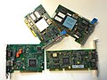
A network switch is networking hardware that connects devices on a computer network by using packet switching to receive and forward data to the destination device.

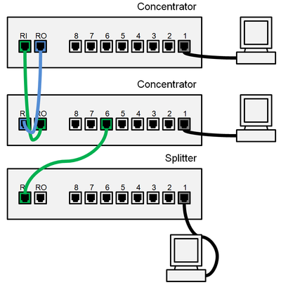
In telecommunication, a distributed-queue dual-bus network (DQDB) is a distributed multi-access network that (a) supports integrated communications using a dual bus and distributed queuing, (b) provides access to local or metropolitan area networks, and (c) supports connectionless data transfer, connection-oriented data transfer, and isochronous communications, such as voice communications.

Fiber Distributed Data Interface

Fiber Distributed Data Interface (FDDI) is a standard for data transmission in a local area network. It uses optical fiber as its standard underlying physical medium, although it was also later specified to use copper cable, in which case it may be called CDDI, standardized as TP-PMD, also referred to as TP-DDI.

The Spanning Tree Protocol (STP) is a network protocol that builds a loop-free logical topology for Ethernet networks. The basic function of STP is to prevent bridge loops and the broadcast radiation that results from them. Spanning tree also allows a network design to include backup links providing fault tolerance if an active link fails.

A virtual LAN (VLAN) is any broadcast domain that is partitioned and isolated in a computer network at the data link layer. LAN is the abbreviation for local area network and in this context virtual refers to a physical object recreated and altered by additional logic. VLANs work by applying tags to network frames and handling these tags in networking systems – creating the appearance and functionality of network traffic that is physically on a single network but acts as if it is split between separate networks. In this way, VLANs can keep network applications separate despite being connected to the same physical network, and without requiring multiple sets of cabling and networking devices to be deployed.

The data link layer, or layer 2, is the second layer of the seven-layer OSI model of computer networking. This layer is the protocol layer that transfers data between nodes on a network segment across the physical layer. The data link layer provides the functional and procedural means to transfer data between network entities and might provide the means to detect and possibly correct errors that may occur in the physical layer.

Medium access control Service layer in IEEE 802 network standards

In IEEE 802 LAN/MAN standards, the medium access control sublayer is the layer that controls the hardware responsible for interaction with the wired, optical or wireless transmission medium. The MAC sublayer and the logical link control (LLC) sublayer together make up the data link layer. Within the data link layer, the LLC provides flow control and multiplexing for the logical link, while the MAC provides flow control and multiplexing for the transmission medium.

In computer networking, promiscuous mode is a mode for a wired network interface controller (NIC) or wireless network interface controller (WNIC) that causes the controller to pass all traffic it receives to the central processing unit (CPU) rather than passing only the frames that the controller is specifically programmed to receive. This mode is normally used for packet sniffing that takes place on a router or on a computer connected to a wired network or one being part of a wireless LAN. Interfaces are placed into promiscuous mode by software bridges often used with hardware virtualization.

IEEE 802.1Q, often referred to as Dot1q, is the networking standard that supports virtual LANs (VLANs) on an IEEE 802.3 Ethernet network. The standard defines a system of VLAN tagging for Ethernet frames and the accompanying procedures to be used by bridges and switches in handling such frames. The standard also contains provisions for a quality-of-service prioritization scheme commonly known as IEEE 802.1p and defines the Generic Attribute Registration Protocol.

Ethernet flow control Technique to suspend transmission to avoid congestion

Ethernet flow control is a mechanism for temporarily stopping the transmission of data on Ethernet family computer networks. The goal of this mechanism is to ensure zero packet loss in the presence of network congestion.

The Link Layer Discovery Protocol (LLDP) is a vendor-neutral link layer protocol used by network devices for advertising their identity, capabilities, and neighbors on a local area network based on IEEE 802 technology, principally wired Ethernet. The protocol is formally referred to by the IEEE as Station and Media Access Control Connectivity Discovery specified in IEEE 802.1AB with additional support in IEEE 802.3 section 6 clause 79.

Provider Backbone Bridges is a set of architecture and protocols for routing over a provider's network allowing interconnection of multiple Provider Bridge Networks without losing each customer's individually defined VLANs. It was initially created by Nortel before being submitted to the IEEE 802.1 committee for standardization. The final standard was approved by the IEEE in June 2008 as IEEE 802.1ah-2008 and has been integrated into IEEE 802.1Q-2011.

In computer networking, an Ethernet frame is a data link layer protocol data unit and uses the underlying Ethernet physical layer transport mechanisms. In other words, a data unit on an Ethernet link transports an Ethernet frame as its payload.

IEEE 802.1ad is an Ethernet networking standard informally known as QinQ as an amendment to IEEE standard IEEE 802.1Q-1998 that was incorporated into the base 802.1Q standard in 2011. The technique is also known as provider bridging, Stacked VLANs, or simply QinQ or Q-in-Q. "Q-in-Q" can for supported devices apply to C-tag stacking on C-tag.

Media-accelerated Global Information Carrier (MaGIC) is an audio over Ethernet protocol developed by Gibson Guitar Corporation in partnership with 3COM. It allows bidirectional transmission of multichannel audio data, control data, and instrument power.

Time-Sensitive Networking (TSN) is a set of standards under development by the Time-Sensitive Networking task group of the IEEE 802.1 working group. The TSN task group was formed in November 2012 by renaming the existing Audio Video Bridging Task Group and continuing its work. The name changed as a result of the extension of the working area of the standardization group. The standards define mechanisms for the time-sensitive transmission of data over deterministic Ethernet networks.

References

  1. "IEEE honors Zurich LAN pioneers", Zurich, Switzerland, 14 April 2003
  2. "Early Token Ring Work at MIT", J. Noel Chiappa, ieeexplore.ieee.org
  3. "A History of Computer Communications 1968-1988", James Pelkey
  4. "Local Area Networks", InfoWorld 24 Mar 1986
  5. IEEE Standards: P802.5 Working Group Area. Ieee802.org. Retrieved on 2011-10-30.
  6. "IEEE 802.3 Local Area Network considerations", IBM document GG22-9422-0
  7. David R. Boggs; Jeffrey C. Mogul; Christopher A. Kent (1988). "Measured capacity of an Ethernet: myths and reality" (PDF). ACM SIGCOMM Computer Communication Review. 25 (1): 123–136. doi:10.1145/205447.205460. S2CID   52820607.
  8. "ETHERNET VS. TOKEN RING IN THE LOCAL AREA NETWORKING BUSINESS", URS VON BURG AND MARTIN KENNY, Industry and Innovation, Volume 10, Number 4, 351–375, December 2003
  9. 1 2 Jonathan Follows (2000). "Token Ring Solutions" (PDF). Redbooks.ibm.com. Archived from the original (PDF) on 2016-08-06. IBM does not view high-speed Token Ring as a requirement for the majority of its customers, and therefore the decision has been made not to provide 100 Mbps high-speed Token Ring uplinks on its products...
  10. IEEE 802.5 activities. Ieee802.org. Retrieved on 2011-10-30.
  11. Louis Ohland. "8228 Multistation Access Unit". Ps-2.kev009.com. Retrieved 2016-08-03.
  12. "What is the difference between an Ethernet hub and switch?" . Retrieved 10 May 2016.
  13. "A Passive Ethernet Hub". Zen22142.zen.co.uk. Retrieved 2016-08-03.
  14. "networking - Duplicate MAC address on the same LAN possible?". Server Fault. 2013-01-03. Retrieved 2016-08-03.
  15. "Does anyone actually still USE Token Ring?", John Sheesley, April 2, 2008, TechRepublic
  16. Bux, W. (1989). "Token-ring local-area networks and their performance". Proceedings of the IEEE . 77 (2): 238. doi:10.1109/5.18625.
  17. 1 2 "Why buy from IBM?" (PDF). Ps-2.kev009.com. Retrieved 2016-08-03.
  18. Louis Ohland. "8226". Ps-2.kev009.com. Retrieved 2016-08-03.
  19. "IBM 8230 Controlled access Unit" (PDF). Public.dhe.ibm.com. Retrieved 2016-08-03.
  20. "Local Area Networks - Token Ring". Scottsnetworkclass.com. Retrieved 2013-06-15.
  21. "Network World". Books.google.ca. IDG Network World Inc. 1991-06-03. p. 56. Retrieved 2016-08-03.
  22. "SG244446" (PDF). Ps-2.kev009.com. Retrieved 2016-08-03.
General