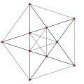
4 21 polytope

Last updated
4 21 t0 E6.svg
421
CDel nodea 1.pngCDel 3a.pngCDel nodea.pngCDel 3a.pngCDel nodea.pngCDel 3a.pngCDel nodea.pngCDel 3a.pngCDel branch.pngCDel 3a.pngCDel nodea.pngCDel 3a.pngCDel nodea.png
1 42 polytope E6 Coxeter plane.svg
142
CDel nodea.pngCDel 3a.pngCDel nodea.pngCDel 3a.pngCDel nodea.pngCDel 3a.pngCDel nodea.pngCDel 3a.pngCDel branch 01lr.pngCDel 3a.pngCDel nodea.pngCDel 3a.pngCDel nodea.png
2 41 t0 E6.svg
241
CDel nodea.pngCDel 3a.pngCDel nodea.pngCDel 3a.pngCDel nodea.pngCDel 3a.pngCDel nodea.pngCDel 3a.pngCDel branch.pngCDel 3a.pngCDel nodea.pngCDel 3a.pngCDel nodea 1.png
4 21 t1 E6.svg
Rectified 421
CDel nodea.pngCDel 3a.pngCDel nodea 1.pngCDel 3a.pngCDel nodea.pngCDel 3a.pngCDel nodea.pngCDel 3a.pngCDel branch.pngCDel 3a.pngCDel nodea.pngCDel 3a.pngCDel nodea.png
4 21 t4 E6.svg
Rectified 142
CDel nodea.pngCDel 3a.pngCDel nodea.pngCDel 3a.pngCDel nodea.pngCDel 3a.pngCDel nodea.pngCDel 3a.pngCDel branch 10.pngCDel 3a.pngCDel nodea.pngCDel 3a.pngCDel nodea.png
2 41 t1 E6.svg
Rectified 241
CDel nodea.pngCDel 3a.pngCDel nodea.pngCDel 3a.pngCDel nodea.pngCDel 3a.pngCDel nodea.pngCDel 3a.pngCDel branch.pngCDel 3a.pngCDel nodea 1.pngCDel 3a.pngCDel nodea.png
4 21 t2 E6.svg
Birectified 421
CDel nodea.pngCDel 3a.pngCDel nodea.pngCDel 3a.pngCDel nodea 1.pngCDel 3a.pngCDel nodea.pngCDel 3a.pngCDel branch.pngCDel 3a.pngCDel nodea.pngCDel 3a.pngCDel nodea.png
4 21 t3 E6.svg
Trirectified 421
CDel nodea.pngCDel 3a.pngCDel nodea.pngCDel 3a.pngCDel nodea.pngCDel 3a.pngCDel nodea 1.pngCDel 3a.pngCDel branch.pngCDel 3a.pngCDel nodea.pngCDel 3a.pngCDel nodea.png
Orthogonal projections in E6 Coxeter plane

In 8-dimensional geometry, the 421 is a semiregular uniform 8-polytope, constructed within the symmetry of the E8 group. It was discovered by Thorold Gosset, published in his 1900 paper. He called it an 8-ic semi-regular figure. [1]

Contents

Its Coxeter symbol is 421, describing its bifurcating Coxeter-Dynkin diagram, with a single ring on the end of the 4-node sequences, CDel nodea 1.pngCDel 3a.pngCDel nodea.pngCDel 3a.pngCDel nodea.pngCDel 3a.pngCDel nodea.pngCDel 3a.pngCDel branch.pngCDel 3a.pngCDel nodea.pngCDel 3a.pngCDel nodea.png.

The rectified 421 is constructed by points at the mid-edges of the 421. The birectified 421 is constructed by points at the triangle face centers of the 421. The trirectified 421 is constructed by points at the tetrahedral centers of the 421.

These polytopes are part of a family of 255 = 28  1 convex uniform 8-polytopes, made of uniform 7-polytope facets and vertex figures, defined by all permutations of one or more rings in this Coxeter-Dynkin diagram: CDel nodea.pngCDel 3a.pngCDel nodea.pngCDel 3a.pngCDel nodea.pngCDel 3a.pngCDel nodea.pngCDel 3a.pngCDel branch.pngCDel 3a.pngCDel nodea.pngCDel 3a.pngCDel nodea.png.

421 polytope

421
Type Uniform 8-polytope
Family k21 polytope
Schläfli symbol {3,3,3,3,32,1}
Coxeter symbol 421
Coxeter diagrams CDel nodea.pngCDel 3a.pngCDel nodea.pngCDel 3a.pngCDel branch.pngCDel 3a.pngCDel nodea.pngCDel 3a.pngCDel nodea.pngCDel 3a.pngCDel nodea.pngCDel 3a.pngCDel nodea 1.png
= CDel nodes 10r.pngCDel 3ab.pngCDel nodes.pngCDel 3ab.pngCDel nodes.pngCDel split5c.pngCDel nodes.png
7-faces19440 total:
2160 411 7-orthoplex.svg
17280 {36} 7-simplex t0.svg
6-faces207360:
138240 {35} 6-simplex t0.svg
69120 {35} 6-simplex t0.svg
5-faces483840 {34} 5-simplex t0.svg
4-faces483840 {33} 4-simplex t0.svg
Cells241920 {3,3} 3-simplex t0.svg
Faces60480 {3} 2-simplex t0.svg
Edges6720
Vertices240
Vertex figure 321 polytope
Petrie polygon 30-gon
Coxeter group E8, [34,2,1], order 696729600
Properties convex

The 421 polytope has 17,280 7-simplex and 2,160 7-orthoplex facets, and 240 vertices. Its vertex figure is the 321 polytope. As its vertices represent the root vectors of the simple Lie group E8, this polytope is sometimes referred to as the E8 root polytope.

The vertices of this polytope can also be obtained by taking the 240 integral octonions of norm 1. Because the octonions are a nonassociative normed division algebra, these 240 points have a multiplication operation making them not into a group but rather a loop, in fact a Moufang loop.

For visualization this 8-dimensional polytope is often displayed in a special skewed orthographic projection direction that fits its 240 vertices within a regular triacontagon (called a Petrie polygon). Its 6720 edges are drawn between the 240 vertices. Specific higher elements (faces, cells, etc.) can also be extracted and drawn on this projection.

Alternate names

Coordinates

It is created by a Wythoff construction upon a set of 8 hyperplane mirrors in 8-dimensional space.

The 240 vertices of the 421 polytope can be constructed in two sets: 112 (22 × 8C2) with coordinates obtained from by taking an arbitrary combination of signs and an arbitrary permutation of coordinates, and 128 roots (27) with coordinates obtained from by taking an even number of minus signs (or, equivalently, requiring that the sum of all the eight coordinates be a multiple of 4).

Each vertex has 56 nearest neighbors; for example, the nearest neighbors of the vertex are those whose coordinates sum to 4, namely the 28 obtained by permuting the coordinates of and the 28 obtained by permuting the coordinates of . These 56 points are the vertices of a 321 polytope in 7 dimensions.

Each vertex has 126 second nearest neighbors: for example, the nearest neighbors of the vertex are those whose coordinates sum to 0, namely the 56 obtained by permuting the coordinates of and the 70 obtained by permuting the coordinates of . These 126 points are the vertices of a 231 polytope in 7 dimensions.

Each vertex also has 56 third nearest neighbors, which are the negatives of its nearest neighbors, and one antipodal vertex, for a total of vertices.


Another construction is by taking signed combination of 14 codewords of 8-bit Extended Hamming code(8,4) that give 14 × 24 = 224 vertices and adding trivial signed axis for last 16 vertices. In this case, vertices are distance of from origin rather than .

 Hamming 8-bit Code  0  0 0 0 0 0 0 0 0  1  1 1 1 1 0 0 0 0   ⇒   ± ± ± ± 0 0 0 0  2  1 1 0 0 1 1 0 0   ⇒   ± ± 0 0 ± ± 0 0  3  0 0 1 1 1 1 0 0   ⇒   0 0 ± ± ± ± 0 0  4  1 0 1 0 1 0 1 0   ⇒   ± 0 ± 0 ± 0 ± 0        ±2 0 0 0 0 0 0 0  5  0 1 0 1 1 0 1 0   ⇒   0 ± 0 ± ± 0 ± 0        0 ±2 0 0 0 0 0 0  6  0 1 1 0 0 1 1 0   ⇒   0 ± ± 0 0 ± ± 0        0 0 ±2 0 0 0 0 0  7  1 0 0 1 0 1 1 0   ⇒   ± 0 0 ± 0 ± ± 0        0 0 0 ±2 0 0 0 0  8  0 1 1 0 1 0 0 1   ⇒   0 ± ± 0 ± 0 0 ±        0 0 0 0 ±2 0 0 0  9  1 0 0 1 1 0 0 1   ⇒   ± 0 0 ± ± 0 0 ±        0 0 0 0 0 ±2 0 0  A  1 0 1 0 0 1 0 1   ⇒   ± 0 ± 0 0 ± 0 ±        0 0 0 0 0 0 ±2 0  B  0 1 0 1 0 1 0 1   ⇒   0 ± 0 ± 0 ± 0 ±        0 0 0 0 0 0 0 ±2  C  1 1 0 0 0 0 1 1   ⇒   ± ± 0 0 0 0 ± ±  D  0 0 1 1 0 0 1 1   ⇒   0 0 ± ± 0 0 ± ±  E  0 0 0 0 1 1 1 1   ⇒   0 0 0 0 ± ± ± ±  F  1 1 1 1 1 1 1 1                           ( 224 vertices     +     16 vertices )

Another decomposition gives the 240 points in 9-dimensions as an expanded 8-simplex, CDel nodes 11.pngCDel 3ab.pngCDel nodes.pngCDel 3ab.pngCDel nodes.pngCDel 3ab.pngCDel branch.png and two opposite birectified 8-simplexes, CDel nodes.pngCDel 3ab.pngCDel nodes.pngCDel 3ab.pngCDel nodes 10lr.pngCDel 3ab.pngCDel branch.png and CDel nodes.pngCDel 3ab.pngCDel nodes.pngCDel 3ab.pngCDel nodes 01lr.pngCDel 3ab.pngCDel branch.png.

 : 72 vertices
 : 84 vertices
 : 84 vertices

This arises similarly to the relation of the A8 lattice and E8 lattice, sharing 8 mirrors of A8: A8-e8 lattice relation.png .

A7 Coxeter plane projections
Name421
CDel nodea.pngCDel 3a.pngCDel nodes.pngCDel split2.pngCDel node.pngCDel 3.pngCDel node.pngCDel 3.pngCDel node.pngCDel 3.pngCDel node.pngCDel 3.pngCDel node 1.png
expanded 8-simplex
CDel nodes 11.pngCDel 3ab.pngCDel nodes.pngCDel 3ab.pngCDel nodes.pngCDel 3ab.pngCDel branch.png
birectified 8-simplex
CDel nodes.pngCDel 3ab.pngCDel nodes.pngCDel 3ab.pngCDel nodes 10lr.pngCDel 3ab.pngCDel branch.png
birectified 8-simplex
CDel nodes.pngCDel 3ab.pngCDel nodes.pngCDel 3ab.pngCDel nodes 01lr.pngCDel 3ab.pngCDel branch.png
Vertices240728484
Image 4 21 t0 A7.svg 8-simplex t07 A7.svg 8-simplex t2 A7.svg

Tessellations

This polytope is the vertex figure for a uniform tessellation of 8-dimensional space, represented by symbol 521 and Coxeter-Dynkin diagram:

CDel nodea 1.pngCDel 3a.pngCDel nodea.pngCDel 3a.pngCDel nodea.pngCDel 3a.pngCDel nodea.pngCDel 3a.pngCDel nodea.pngCDel 3a.pngCDel branch.pngCDel 3a.pngCDel nodea.pngCDel 3a.pngCDel nodea.png

Construction and faces

The facet information of this polytope can be extracted from its Coxeter-Dynkin diagram:

CDel nodea.pngCDel 3a.pngCDel nodea.pngCDel 3a.pngCDel branch.pngCDel 3a.pngCDel nodea.pngCDel 3a.pngCDel nodea.pngCDel 3a.pngCDel nodea.pngCDel 3a.pngCDel nodea 1.png

Removing the node on the short branch leaves the 7-simplex:

CDel nodea.pngCDel 3a.pngCDel nodea.pngCDel 3a.pngCDel nodea.pngCDel 3a.pngCDel nodea.pngCDel 3a.pngCDel nodea.pngCDel 3a.pngCDel nodea.pngCDel 3a.pngCDel nodea 1.png

Removing the node on the end of the 2-length branch leaves the 7-orthoplex in its alternated form (411):

CDel nodea.pngCDel 3a.pngCDel branch.pngCDel 3a.pngCDel nodea.pngCDel 3a.pngCDel nodea.pngCDel 3a.pngCDel nodea.pngCDel 3a.pngCDel nodea 1.png

Every 7-simplex facet touches only 7-orthoplex facets, while alternate facets of an orthoplex facet touch either a simplex or another orthoplex. There are 17,280 simplex facets and 2160 orthoplex facets.

Since every 7-simplex has 7 6-simplex facets, each incident to no other 6-simplex, the 421 polytope has 120,960 (7×17,280) 6-simplex faces that are facets of 7-simplexes. Since every 7-orthoplex has 128 (27) 6-simplex facets, half of which are not incident to 7-simplexes, the 421 polytope has 138,240 (26×2160) 6-simplex faces that are not facets of 7-simplexes. The 421 polytope thus has two kinds of 6-simplex faces, not interchanged by symmetries of this polytope. The total number of 6-simplex faces is 259200 (120,960+138,240).

The vertex figure of a single-ring polytope is obtained by removing the ringed node and ringing its neighbor(s). This makes the 321 polytope.

CDel nodea.pngCDel 3a.pngCDel nodea.pngCDel 3a.pngCDel branch.pngCDel 3a.pngCDel nodea.pngCDel 3a.pngCDel nodea.pngCDel 3a.pngCDel nodea 1.png

Seen in a configuration matrix, the element counts can be derived by mirror removal and ratios of Coxeter group orders. [4]

Projections

E8-with-thread.jpg
The 421 graph created as string art.
E8Petrie.svg
E8 Coxeter plane projection

3D

Zome-like.png
Mathematical representation of the physical Zome model isomorphic (?) to E8. This is constructed from VisibLie_E8 pictured with all 3360 edges of length 2(51) from two concentric 600-cells (at the golden ratio) with orthogonal projections to perspective 3-space
E8 3D.png
The actual split real even E8 421 polytope projected into perspective 3-space pictured with all 6720 edges of length 2 [5]
E8-3Dprint-b.png E8 rotated to H4+H4φ, projected to 3D, converted to STL, and printed in nylon plastic. Projection basis used:
x = {1, φ, 0, 1, φ, 0,0,0}
y = {φ, 0, 1, φ, 0, 1,0,0}
z = {0, 1, φ, 0, 1, φ,0,0}

2D

These graphs represent orthographic projections in the E8, E7, E6, and B8, D8, D7, D6, D5, D4, D3, A7, A5 Coxeter planes. The vertex colors are by overlapping multiplicity in the projection: colored by increasing order of multiplicities as red, orange, yellow, green.

k21 family

The 421 polytope is last in a family called the k21 polytopes. The first polytope in this family is the semiregular triangular prism which is constructed from three squares (2-orthoplexes) and two triangles (2-simplexes).

Geometric folding

The 421 polytope can be projected into 3-space as a physical vertex-edge model. Pictured here as 2 concentric 600-cells (at the golden ratio) using Zome tools. (Not all of the 3360 edges of length [?]2([?]5-1) are represented.) E8 roots zome.jpg
The 421 polytope can be projected into 3-space as a physical vertex-edge model. Pictured here as 2 concentric 600-cells (at the golden ratio) using Zome tools. (Not all of the 3360 edges of length 2(5-1) are represented.)

The 421 is related to the 600-cell by a geometric folding of the Coxeter-Dynkin diagrams. This can be seen in the E8/H4 Coxeter plane projections. The 240 vertices of the 421 polytope are projected into 4-space as two copies of the 120 vertices of the 600-cell, one copy smaller (scaled by the golden ratio) than the other with the same orientation. Seen as a 2D orthographic projection in the E8/H4 Coxeter plane, the 120 vertices of the 600-cell are projected in the same four rings as seen in the 421. The other 4 rings of the 421 graph also match a smaller copy of the four rings of the 600-cell.

In 4-dimensional complex geometry, the regular complex polytope 3{3}3{3}3{3}3, and Coxeter diagram CDel 3node 1.pngCDel 3.pngCDel 3node.pngCDel 3.pngCDel 3node.pngCDel 3.pngCDel 3node.png exists with the same vertex arrangement as the 421 polytope. It is self-dual. Coxeter called it the Witting polytope, after Alexander Witting. Coxeter expresses its Shephard group symmetry by 3[3]3[3]3[3]3. [7]

The 421 is sixth in a dimensional series of semiregular polytopes. Each progressive uniform polytope is constructed vertex figure of the previous polytope. Thorold Gosset identified this series in 1900 as containing all regular polytope facets, containing all simplexes and orthoplexes.

k21 figures in n dimensions
SpaceFiniteEuclideanHyperbolic
En 3 4 5 6 7 8 9 10
Coxeter
group
E3=A2A1E4=A4E5=D5 E6 E7 E8 E9 = = E8+E10 = = E8++
Coxeter
diagram
CDel node.pngCDel 3.pngCDel node 1.pngCDel 2.pngCDel node 1.pngCDel nodea.pngCDel 3a.pngCDel nodea.pngCDel 3a.pngCDel branch 10.pngCDel nodea.pngCDel 3a.pngCDel nodea.pngCDel 3a.pngCDel branch.pngCDel 3a.pngCDel nodea 1.pngCDel nodea.pngCDel 3a.pngCDel nodea.pngCDel 3a.pngCDel branch.pngCDel 3a.pngCDel nodea.pngCDel 3a.pngCDel nodea 1.pngCDel nodea.pngCDel 3a.pngCDel nodea.pngCDel 3a.pngCDel branch.pngCDel 3a.pngCDel nodea.pngCDel 3a.pngCDel nodea.pngCDel 3a.pngCDel nodea 1.pngCDel nodea.pngCDel 3a.pngCDel nodea.pngCDel 3a.pngCDel branch.pngCDel 3a.pngCDel nodea.pngCDel 3a.pngCDel nodea.pngCDel 3a.pngCDel nodea.pngCDel 3a.pngCDel nodea 1.pngCDel nodea.pngCDel 3a.pngCDel nodea.pngCDel 3a.pngCDel branch.pngCDel 3a.pngCDel nodea.pngCDel 3a.pngCDel nodea.pngCDel 3a.pngCDel nodea.pngCDel 3a.pngCDel nodea.pngCDel 3a.pngCDel nodea 1.pngCDel nodea.pngCDel 3a.pngCDel nodea.pngCDel 3a.pngCDel branch.pngCDel 3a.pngCDel nodea.pngCDel 3a.pngCDel nodea.pngCDel 3a.pngCDel nodea.pngCDel 3a.pngCDel nodea.pngCDel 3a.pngCDel nodea.pngCDel 3a.pngCDel nodea 1.png
Symmetry [3−1,2,1][30,2,1][31,2,1][32,2,1][33,2,1][34,2,1][35,2,1][36,2,1]
Order 121201,92051,8402,903,040696,729,600
Graph Triangular prism.png 4-simplex t1.svg Demipenteract graph ortho.svg E6 graph.svg E7 graph.svg E8 graph.svg --
Name 121 021 121 221 321 421 521 621

Rectified 4_21 polytope

Rectified 421
Type Uniform 8-polytope
Schläfli symbol t1{3,3,3,3,32,1}
Coxeter symbol t1(421)
Coxeter diagram CDel nodea.pngCDel 3a.pngCDel nodea.pngCDel 3a.pngCDel branch.pngCDel 3a.pngCDel nodea.pngCDel 3a.pngCDel nodea.pngCDel 3a.pngCDel nodea 1.pngCDel 3a.pngCDel nodea.png
7-faces19680 total:

240 321
17280 t1{36}
2160 t1{35,4}

6-faces375840
5-faces1935360
4-faces3386880
Cells2661120
Faces1028160
Edges181440
Vertices6720
Vertex figure 221 prism
Coxeter group E8, [34,2,1]
Properties convex

The rectified 421 can be seen as a rectification of the 421 polytope, creating new vertices on the center of edges of the 421.

Alternative names

Construction

It is created by a Wythoff construction upon a set of 8 hyperplane mirrors in 8-dimensional space. It is named for being a rectification of the 421. Vertices are positioned at the midpoint of all the edges of 421, and new edges connecting them.

The facet information can be extracted from its Coxeter-Dynkin diagram.

CDel nodea.pngCDel 3a.pngCDel nodea.pngCDel 3a.pngCDel branch.pngCDel 3a.pngCDel nodea.pngCDel 3a.pngCDel nodea.pngCDel 3a.pngCDel nodea 1.pngCDel 3a.pngCDel nodea.png

Removing the node on the short branch leaves the rectified 7-simplex:

CDel nodea.pngCDel 3a.pngCDel nodea.pngCDel 3a.pngCDel nodea.pngCDel 3a.pngCDel nodea.pngCDel 3a.pngCDel nodea.pngCDel 3a.pngCDel nodea 1.pngCDel 3a.pngCDel nodea.png

Removing the node on the end of the 2-length branch leaves the rectified 7-orthoplex in its alternated form:

CDel nodea.pngCDel 3a.pngCDel branch.pngCDel 3a.pngCDel nodea.pngCDel 3a.pngCDel nodea.pngCDel 3a.pngCDel nodea 1.pngCDel 3a.pngCDel nodea.png

Removing the node on the end of the 4-length branch leaves the 321:

CDel nodea.pngCDel 3a.pngCDel nodea.pngCDel 3a.pngCDel branch.pngCDel 3a.pngCDel nodea.pngCDel 3a.pngCDel nodea.pngCDel 3a.pngCDel nodea 1.png

The vertex figure is determined by removing the ringed node and adding a ring to the neighboring node. This makes a 221 prism.

CDel nodea.pngCDel 3a.pngCDel nodea.pngCDel 3a.pngCDel branch.pngCDel 3a.pngCDel nodea.pngCDel 3a.pngCDel nodea 1.pngCDel 2.pngCDel nodea 1.png

Coordinates

The Cartesian coordinates of the 6720 vertices of the rectified 421 is given by all permutations of coordinates from three other uniform polytope:

D8 Coxeter plane projections
NameRectified 421
CDel nodea.pngCDel 3a.pngCDel nodes.pngCDel split2.pngCDel node.pngCDel 3.pngCDel node.pngCDel 3.pngCDel node.pngCDel 3.pngCDel node 1.pngCDel 3.pngCDel node.png
birectified 8-cube
CDel nodes.pngCDel split2.pngCDel node 1.pngCDel 3.pngCDel node.pngCDel 3.pngCDel node.pngCDel 3.pngCDel node.pngCDel 3.pngCDel node.pngCDel 3.pngCDel node.png = CDel node.pngCDel 4.pngCDel node.pngCDel 3.pngCDel node 1.pngCDel 3.pngCDel node.pngCDel 3.pngCDel node.pngCDel 3.pngCDel node.pngCDel 3.pngCDel node.pngCDel 3.pngCDel node.png
hexic 8-cube
CDel nodes 10ru.pngCDel split2.pngCDel node.pngCDel 3.pngCDel node.pngCDel 3.pngCDel node.pngCDel 3.pngCDel node.pngCDel 3.pngCDel node 1.pngCDel 3.pngCDel node.png = CDel node h1.pngCDel 4.pngCDel node.pngCDel 3.pngCDel node.pngCDel 3.pngCDel node.pngCDel 3.pngCDel node.pngCDel 3.pngCDel node.pngCDel 3.pngCDel node 1.pngCDel 3.pngCDel node.png
cantellated 8-orthoplex
CDel nodes.pngCDel split2.pngCDel node.pngCDel 3.pngCDel node.pngCDel 3.pngCDel node.pngCDel 3.pngCDel node 1.pngCDel 3.pngCDel node.pngCDel 3.pngCDel node 1.png = CDel node.pngCDel 4.pngCDel node.pngCDel 3.pngCDel node.pngCDel 3.pngCDel node.pngCDel 3.pngCDel node.pngCDel 3.pngCDel node 1.pngCDel 3.pngCDel node.pngCDel 3.pngCDel node 1.png
Vertices6720179235841344
Image 4 21 t1 B7.svg 8-cube t2 B7.svg 8-demicube t05 D8.svg 8-cube t57 B7.svg

Projections

2D

These graphs represent orthographic projections in the E8, E7, E6, and B8, D8, D7, D6, D5, D4, D3, A7, A5 Coxeter planes. The vertex colors are by overlapping multiplicity in the projection: colored by increasing order of multiplicities as red, orange, yellow, green.

Birectified 4_21 polytope

Birectified 421 polytope
Type Uniform 8-polytope
Schläfli symbol t2{3,3,3,3,32,1}
Coxeter symbol t2(421)
Coxeter diagram CDel nodea.pngCDel 3a.pngCDel nodea.pngCDel 3a.pngCDel branch.pngCDel 3a.pngCDel nodea.pngCDel 3a.pngCDel nodea 1.pngCDel 3a.pngCDel nodea.pngCDel 3a.pngCDel nodea.png
7-faces19680 total:

17280 t2{36} 7-simplex t2.svg
2160 t2{35,4} 7-cube t4.svg
240 t1(321) Up2 3 21 t1 E7.svg

6-faces382560
5-faces2600640
4-faces7741440
Cells9918720
Faces5806080
Edges1451520
Vertices60480
Vertex figure 5-demicube-triangular duoprism
Coxeter group E8, [34,2,1]
Properties convex

The birectified 421 can be seen as a second rectification of the uniform 421 polytope. Vertices of this polytope are positioned at the centers of all the 60480 triangular faces of the 421.

Alternative names

Construction

It is created by a Wythoff construction upon a set of 8 hyperplane mirrors in 8-dimensional space. It is named for being a birectification of the 421. Vertices are positioned at the center of all the triangle faces of 421.

The facet information can be extracted from its Coxeter-Dynkin diagram.

CDel nodea.pngCDel 3a.pngCDel nodea.pngCDel 3a.pngCDel branch.pngCDel 3a.pngCDel nodea.pngCDel 3a.pngCDel nodea 1.pngCDel 3a.pngCDel nodea.pngCDel 3a.pngCDel nodea.png

Removing the node on the short branch leaves the birectified 7-simplex. There are 17280 of these facets.

CDel nodea.pngCDel 3a.pngCDel nodea.pngCDel 3a.pngCDel nodea.pngCDel 3a.pngCDel nodea.pngCDel 3a.pngCDel nodea 1.pngCDel 3a.pngCDel nodea.pngCDel 3a.pngCDel nodea.png

Removing the node on the end of the 2-length branch leaves the birectified 7-orthoplex in its alternated form. There are 2160 of these facets.

CDel nodea.pngCDel 3a.pngCDel branch.pngCDel 3a.pngCDel nodea.pngCDel 3a.pngCDel nodea 1.pngCDel 3a.pngCDel nodea.pngCDel 3a.pngCDel nodea.png

Removing the node on the end of the 4-length branch leaves the rectified 321. There are 240 of these facets.

CDel nodea.pngCDel 3a.pngCDel nodea.pngCDel 3a.pngCDel branch.pngCDel 3a.pngCDel nodea.pngCDel 3a.pngCDel nodea 1.pngCDel 3a.pngCDel nodea.png

The vertex figure is determined by removing the ringed node and adding rings to the neighboring nodes. This makes a 5-demicube-triangular duoprism.

CDel nodea.pngCDel 3a.pngCDel nodea.pngCDel 3a.pngCDel branch.pngCDel 3a.pngCDel nodea 1.pngCDel 2.pngCDel nodea 1.pngCDel 3a.pngCDel nodea.png

Projections

2D

These graphs represent orthographic projections in the E8, E7, E6, and B8, D8, D7, D6, D5, D4, D3, A7, A5 Coxeter planes. Edges are not drawn. The vertex colors are by overlapping multiplicity in the projection: colored by increasing order of multiplicities as red, orange, yellow, green, etc.

Trirectified 4_21 polytope

Trirectified 421 polytope
Type Uniform 8-polytope
Schläfli symbol t3{3,3,3,3,32,1}
Coxeter symbol t3(421)
Coxeter diagram CDel nodea.pngCDel 3a.pngCDel nodea.pngCDel 3a.pngCDel branch.pngCDel 3a.pngCDel nodea 1.pngCDel 3a.pngCDel nodea.pngCDel 3a.pngCDel nodea.pngCDel 3a.pngCDel nodea.png
7-faces19680
6-faces382560
5-faces2661120
4-faces9313920
Cells16934400
Faces14515200
Edges4838400
Vertices241920
Vertex figure tetrahedron-rectified 5-cell duoprism
Coxeter group E8, [34,2,1]
Properties convex

Alternative names

Construction

It is created by a Wythoff construction upon a set of 8 hyperplane mirrors in 8-dimensional space. It is named for being a birectification of the 421. Vertices are positioned at the center of all the triangle faces of 421.

The facet information can be extracted from its Coxeter-Dynkin diagram.

CDel nodea.pngCDel 3a.pngCDel nodea.pngCDel 3a.pngCDel branch.pngCDel 3a.pngCDel nodea 1.pngCDel 3a.pngCDel nodea.pngCDel 3a.pngCDel nodea.pngCDel 3a.pngCDel nodea.png

Removing the node on the short branch leaves the trirectified 7-simplex:

CDel nodea.pngCDel 3a.pngCDel nodea.pngCDel 3a.pngCDel nodea.pngCDel 3a.pngCDel nodea 1.pngCDel 3a.pngCDel nodea.pngCDel 3a.pngCDel nodea.pngCDel 3a.pngCDel nodea.png

Removing the node on the end of the 2-length branch leaves the trirectified 7-orthoplex in its alternated form:

CDel nodea.pngCDel 3a.pngCDel branch.pngCDel 3a.pngCDel nodea 1.pngCDel 3a.pngCDel nodea.pngCDel 3a.pngCDel nodea.pngCDel 3a.pngCDel nodea.png

Removing the node on the end of the 4-length branch leaves the birectified 321:

CDel nodea.pngCDel 3a.pngCDel nodea.pngCDel 3a.pngCDel branch.pngCDel 3a.pngCDel nodea 1.pngCDel 3a.pngCDel nodea.pngCDel 3a.pngCDel nodea.png

The vertex figure is determined by removing the ringed node and ring the neighbor nodes. This makes a tetrahedron-rectified 5-cell duoprism.

CDel nodea.pngCDel 3a.pngCDel nodea.pngCDel 3a.pngCDel branch 10.pngCDel 2.pngCDel nodea 1.pngCDel 3a.pngCDel nodea.pngCDel 3a.pngCDel nodea.png

Projections

2D

These graphs represent orthographic projections in the E7, E6, B8, D8, D7, D6, D5, D4, D3, A7, and A5 Coxeter planes. The vertex colors are by overlapping multiplicity in the projection: colored by increasing order of multiplicities as red, orange, yellow, green.

(E8 and B8 were too large to display)

See also

Notes

  1. 1 2 Gosset, 1900
  2. Elte, 1912
  3. Klitzing, (o3o3o3o *c3o3o3o3x - fy)
  4. Coxeter, Regular Polytopes, 11.8 Gossett figures in six, seven, and eight dimensions, p. 202-203
  5. e8Flyer.nb
  6. David Richter: Gosset's Figure in 8 Dimensions, A Zome Model
  7. Coxeter Regular Convex Polytopes, 12.5 The Witting polytope
  8. Klitzing, (o3o3o3o *c3o3o3x3o - riffy)
  9. "Sotho".
  10. "Bro".
  11. "Srek".
  12. Klitzing, (o3o3o3o *c3o3x3o3o - borfy)
  13. Klitzing, (o3o3o3o *c3x3o3o3o - torfy)

Related Research Articles

<span class="mw-page-title-main">Gosset–Elte figures</span>

In geometry, the Gosset–Elte figures, named by Coxeter after Thorold Gosset and E. L. Elte, are a group of uniform polytopes which are not regular, generated by a Wythoff construction with mirrors all related by order-2 and order-3 dihedral angles. They can be seen as one-end-ringed Coxeter–Dynkin diagrams.

In geometry, a uniform k21 polytope is a polytope in k + 4 dimensions constructed from the En Coxeter group, and having only regular polytope facets. The family was named by their Coxeter symbol k21 by its bifurcating Coxeter–Dynkin diagram, with a single ring on the end of the k-node sequence.

<span class="mw-page-title-main">Rectified 5-simplexes</span>

In five-dimensional geometry, a rectified 5-simplex is a convex uniform 5-polytope, being a rectification of the regular 5-simplex.

2<sub> 31</sub> polytope Uniform Polytope

In 7-dimensional geometry, 231 is a uniform polytope, constructed from the E7 group.

1<sub> 22</sub> polytope Uniform 6-polytope

In 6-dimensional geometry, the 122 polytope is a uniform polytope, constructed from the E6 group. It was first published in E. L. Elte's 1912 listing of semiregular polytopes, named as V72 (for its 72 vertices).

1<sub> 32</sub> polytope Uniform polytope

In 7-dimensional geometry, 132 is a uniform polytope, constructed from the E7 group.

1 <sub>42</sub> polytope

In 8-dimensional geometry, the 142 is a uniform 8-polytope, constructed within the symmetry of the E8 group.

2<sub> 41</sub> polytope

In 8-dimensional geometry, the 241 is a uniform 8-polytope, constructed within the symmetry of the E8 group.

2<sub> 21</sub> polytope

In 6-dimensional geometry, the 221 polytope is a uniform 6-polytope, constructed within the symmetry of the E6 group. It was discovered by Thorold Gosset, published in his 1900 paper. He called it an 6-ic semi-regular figure. It is also called the Schläfli polytope.

3<sub> 21</sub> polytope

In 7-dimensional geometry, the 321 polytope is a uniform 7-polytope, constructed within the symmetry of the E7 group. It was discovered by Thorold Gosset, published in his 1900 paper. He called it an 7-ic semi-regular figure.

In geometry, the 222 honeycomb is a uniform tessellation of the six-dimensional Euclidean space. It can be represented by the Schläfli symbol {3,3,32,2}. It is constructed from 221 facets and has a 122 vertex figure, with 54 221 polytopes around every vertex.

<span class="mw-page-title-main">Stericated 5-simplexes</span>

In five-dimensional geometry, a stericated 5-simplex is a convex uniform 5-polytope with fourth-order truncations (sterication) of the regular 5-simplex.

<span class="mw-page-title-main">Pentellated 6-simplexes</span> Uniform 6-polytope

In six-dimensional geometry, a pentellated 6-simplex is a convex uniform 6-polytope with 5th order truncations of the regular 6-simplex.

In seven-dimensional geometry, a rectified 7-orthoplex is a convex uniform 7-polytope, being a rectification of the regular 7-orthoplex.

<span class="mw-page-title-main">Rectified 6-simplexes</span>

In six-dimensional geometry, a rectified 6-simplex is a convex uniform 6-polytope, being a rectification of the regular 6-simplex.

In geometry, the 521 honeycomb is a uniform tessellation of 8-dimensional Euclidean space. The symbol 521 is from Coxeter, named for the length of the 3 branches of its Coxeter-Dynkin diagram.

<span class="mw-page-title-main">Rectified 7-simplexes</span> Convex uniform 7-polytope in seven-dimensional geometry

In seven-dimensional geometry, a rectified 7-simplex is a convex uniform 7-polytope, being a rectification of the regular 7-simplex.

<span class="mw-page-title-main">Rectified 8-simplexes</span>

In eight-dimensional geometry, a rectified 8-simplex is a convex uniform 8-polytope, being a rectification of the regular 8-simplex.

In nine-dimensional geometry, a rectified 9-simplex is a convex uniform 9-polytope, being a rectification of the regular 9-orthoplex.

In geometry, an E9 honeycomb is a tessellation of uniform polytopes in hyperbolic 9-dimensional space. , also (E10) is a paracompact hyperbolic group, so either facets or vertex figures will not be bounded.

References

Family An Bn I2(p) / Dn E6 / E7 / E8 / F4 / G2 Hn
Regular polygon Triangle Square p-gon Hexagon Pentagon
Uniform polyhedron Tetrahedron OctahedronCube Demicube DodecahedronIcosahedron
Uniform polychoron Pentachoron 16-cellTesseract Demitesseract 24-cell 120-cell600-cell
Uniform 5-polytope 5-simplex 5-orthoplex5-cube 5-demicube
Uniform 6-polytope 6-simplex 6-orthoplex6-cube 6-demicube 122221
Uniform 7-polytope 7-simplex 7-orthoplex7-cube 7-demicube 132231321
Uniform 8-polytope 8-simplex 8-orthoplex8-cube 8-demicube 142241421
Uniform 9-polytope 9-simplex 9-orthoplex9-cube 9-demicube
Uniform 10-polytope 10-simplex 10-orthoplex10-cube 10-demicube
Uniform n-polytope n-simplex n-orthoplexn-cube n-demicube 1k22k1k21 n-pentagonal polytope
Topics: Polytope familiesRegular polytopeList of regular polytopes and compounds