In geography, latitude is a coordinate that specifies the north–south position of a point on the surface of the Earth or another celestial body. Latitude is given as an angle that ranges from −90° at the south pole to 90° at the north pole, with 0° at the Equator. Lines of constant latitude, or parallels, run east–west as circles parallel to the equator. Latitude and longitude are used together as a coordinate pair to specify a location on the surface of the Earth.

The Mercator projection is a conformal cylindrical map projection first presented by Flemish geographer and mapmaker Gerardus Mercator in 1569. In the 18th century, it became the standard map projection for navigation due to its property of representing rhumb lines as straight lines. When applied to world maps, the Mercator projection inflates the size of lands the further they are from the equator. Therefore, landmasses such as Greenland and Antarctica appear far larger than they actually are relative to landmasses near the equator. Nowadays the Mercator projection is widely used because, aside from marine navigation, it is well suited for internet web maps.

In astronomy, coordinate systems are used for specifying positions of celestial objects relative to a given reference frame, based on physical reference points available to a situated observer. Coordinate systems in astronomy can specify an object's relative position in three-dimensional space or plot merely by its direction on a celestial sphere, if the object's distance is unknown or trivial.

A sundial is a horological device that tells the time of day when direct sunlight shines by the apparent position of the Sun in the sky. In the narrowest sense of the word, it consists of a flat plate and a gnomon, which casts a shadow onto the dial. As the Sun appears to move through the sky, the shadow aligns with different hour-lines, which are marked on the dial to indicate the time of day. The style is the time-telling edge of the gnomon, though a single point or nodus may be used. The gnomon casts a broad shadow; the shadow of the style shows the time. The gnomon may be a rod, wire, or elaborately decorated metal casting. The style must be parallel to the axis of the Earth's rotation for the sundial to be accurate throughout the year. The style's angle from horizontal is equal to the sundial's geographical latitude.

In geometry, a solid angle is a measure of the amount of the field of view from some particular point that a given object covers. That is, it is a measure of how large the object appears to an observer looking from that point. The point from which the object is viewed is called the apex of the solid angle, and the object is said to subtend its solid angle at that point.

The great-circle distance, orthodromic distance, or spherical distance is the distance between two points on a sphere, measured along the great-circle arc between them. This arc is the shortest path between the two points on the surface of the sphere.

In non-Euclidean geometry, the Poincaré half-plane model is a way of representing the hyperbolic plane using points in the familiar Euclidean plane. Specifically, each point in the hyperbolic plane is represented using a Euclidean point with coordinates whose coordinate is greater than zero, the upper half-plane, and a metric tensor called the Poincaré metric is adopted, in which the local scale is inversely proportional to the coordinate. Points on the -axis, whose coordinate is equal to zero, represent ideal points, which are outside the hyperbolic plane proper.
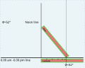
The solar zenith angle is the zenith angle of the sun, i.e., the angle between the sun’s rays and the vertical direction. It is the complement to the solar altitude or solar elevation, which is the altitude angle or elevation angle between the sun’s rays and a horizontal plane. At solar noon, the zenith angle is at a minimum and is equal to latitude minus solar declination angle. This is the basis by which ancient mariners navigated the oceans.
The solar azimuth angle is the azimuth of the Sun's position. This horizontal coordinate defines the Sun's relative direction along the local horizon, whereas the solar zenith angle defines the Sun's apparent altitude.
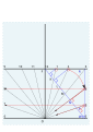
In algebraic geometry, the trisectrix of Maclaurin is a cubic plane curve notable for its trisectrix property, meaning it can be used to trisect an angle. It can be defined as locus of the point of intersection of two lines, each rotating at a uniform rate about separate points, so that the ratio of the rates of rotation is 1:3 and the lines initially coincide with the line between the two points. A generalization of this construction is called a sectrix of Maclaurin. The curve is named after Colin Maclaurin who investigated the curve in 1742.

Great-circle navigation or orthodromic navigation is the practice of navigating a vessel along a great circle. Such routes yield the shortest distance between two points on the globe.

Magnetic dip, dip angle, or magnetic inclination is the angle made with the horizontal by Earth's magnetic field lines. This angle varies at different points on Earth's surface. Positive values of inclination indicate that the magnetic field of Earth is pointing downward, into Earth, at the point of measurement, and negative values indicate that it is pointing upward. The dip angle is in principle the angle made by the needle of a vertically held compass, though in practice ordinary compass needles may be weighted against dip or may be unable to move freely in the correct plane. The value can be measured more reliably with a special instrument typically known as a dip circle.

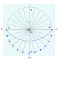
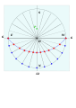
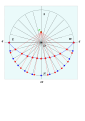
Analemmatic sundials are a type of horizontal sundial that has a vertical gnomon and hour markers positioned in an elliptical pattern. The gnomon is not fixed and must change position daily to accurately indicate time of day. Hence there are no hour lines on the dial and the time of day is read only on the ellipse. As with most sundials, analemmatic sundials mark solar time rather than clock time.
François-Lamathe Dom Bédos de Celles de Salelles was a Benedictine monk best known for being a master pipe organ builder.

Geographical distance or geodetic distance is the distance measured along the surface of the Earth, or the shortest arch length.

The Whitehurst & Son sundial was produced in Derby in 1812 by the nephew of John Whitehurst. It is a fine example of a precision sundial telling local apparent time with a scale to convert this to local mean time, and is accurate to the nearest minute. The sundial is now housed in the Derby Museum and Art Gallery.

A bifilar dial is a type of sundial invented by the German mathematician Hugo Michnik in 1922. It has two non-touching threads parallel to the dial. Usually the second thread is orthogonal-(perpendicular) to the first. The intersection of the two threads' shadows gives the local apparent time.
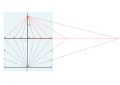
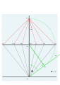
Dialing scales are used to lay out the face of a sundial geometrically. They were proposed by Samuel Foster in 1638, and produced by George Serle and Anthony Thompson in 1658 on a ruler. There are two scales: the latitude scale and the hour scale. They can be used to draw all gnomonic dials – and reverse engineer existing dials to discover their original intended location.

A London dial in the broadest sense can mean any sundial that is set for 51°30′ N, but more specifically refers to a engraved brass horizontal sundial with a distinctive design. London dials were originally engraved by scientific instrument makers. The trade was heavily protected by the system of craft guilds.

Vertical declining dials are sundials that indicate local apparent time. Vertical south dials are a special case: as are vertical north, vertical east and vertical west dials. The word declining means that the wall is offset from one of these 4 cardinal points. There are dials that are not vertical, and these are called reclining dials.


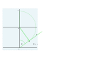
 Setting out a dial for 52°N. The three initial lines.
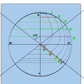
 Marking the latitude, laying out length , and copying to G on the vertical.
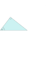
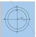
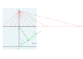 A tangent:Laying out the length