Saturn Launch Vehicle Digital Computer

Last updated
LVDC from Instrument Unit technical manual LaunchVehicleDigitalComputer-600.jpg
LVDC from Instrument Unit technical manual

The Saturn Launch Vehicle Digital Computer (LVDC) was a computer that provided the autopilot for the Saturn V rocket from launch to Earth orbit insertion. Designed and manufactured by IBM's Electronics Systems Center in Owego, N.Y., it was one of the major components of the Instrument Unit, fitted to the S-IVB stage of the Saturn V and Saturn IB rockets. The LVDC also supported pre- and post-launch checkout of the Saturn hardware. It was used in conjunction with the Launch Vehicle Data Adaptor (LVDA) which performed signal conditioning to the sensor inputs to the computer from the launch vehicle.

Contents

Hardware

The LVDC was capable of executing 12190 instructions per second. For comparison, a 2012-era microprocessor can execute 4 instructions per cycle at 3 GHz, achieving 12 billion instructions per second, one million times faster.

Its master clock ran at 2.048 MHz, but operations were performed bit-serially, with 4 cycles required to process each bit, 14 bits per phase, and 3 phases per instruction, for a basic time of 168 cycles = 82 μs for a simple add. (A few instructions, such as multiply or divide, took a few times this value.)

Memory was in the form of 13-bit syllables, each with a 14th parity bit. [1] Instructions were one syllable in size, while data words were two syllables (26 bits). Main memory was random access magnetic core, in the form of 4,096-word memory modules. Up to 8 modules provided a maximum of 32,768 words of memory. Ultrasonic delay lines provided temporary storage.

For reliability, the LVDC used triple-redundant logic and a voting system. The computer included three identical logic systems. Each logic system was split into a seven-stage pipeline. At each stage in the pipeline, a voting system would take a majority vote on the results, with the most popular result being passed on to the next stage in all pipelines. This meant that, for each of the seven stages, one module in any one of the three pipelines could fail, and the LVDC would still produce the correct results. The result was an estimated reliability of 99.6% over 250 hours of operation, which was far more than the few hours required for an Apollo mission.

With four memory modules, giving a total capacity of 16,384 words, the computer weighed 72.5 lb (32.9 kg), was 29.5×12.5×10.5 inches in size (74×32×27 cm) and consumed 137 watts.

Software architecture and algorithms

LVDC instruction words were split into a 4-bit opcode field (least-significant bits) and a 9-bit operand address field (most-significant bits). This left it with sixteen possible opcode values when there were eighteen different instructions: consequently, three of the instructions used the same opcode value, and used two bits of the address value to determine which instruction was executed.

Memory was broken into 256-word "sectors". 8 bits of the address specified a word within a sector, and the 9th bit selected between the software-selectable "current sector" or a global sector called "residual memory".

The eighteen possible LVDC instructions were: [2] :20-101

InstructionOpcodeFunction
HOP0000Transfer execution to a different part of the program. Unlike a modern 'jump' instruction the operand address did not actually specify the address to jump to, but pointed to a 26-bit 'HOP constant' which specified the address.
MPY0001Multiply the contents of the memory location specified in the operand address by the contents of the accumulator register. This instruction took four instruction cycles to complete, but didn't stall program execution, so other instructions could execute before it finished. The result was left in a known register.
SUB0010Subtract the contents of the memory location specified in the operand address from the accumulator register.
DIV0011Divide the contents of the memory location specified in the operand address into the accumulator. This instruction took eight instruction cycles to complete, but didn't stall program execution.
TNZ0100Transfers instruction execution to the operand address specified if the accumulator contents are not zero.
MPH0101Multiply the contents of the memory location specified in the operand address by the contents of the accumulator register. Unlike MPY, this instruction does halt execution until the multiplication is complete.
AND0110Logically AND the contents of the accumulator with the contents of the memory location specified in the operand address.
ADD0111Add the contents of the memory location specified in the operand address to the accumulator register.
TRA1000Transfer execution to the memory location specified in the operand address. The address is within the current instruction sector; the 9th (residual) bit of the operand selects the syllable.
XOR1001Logically XOR the contents of the accumulator with the contents of the memory location specified in the operand address.
PIO1010Process input or output: communicate with external hardware via the Data Adapter. "The low order address bits, A1 and A2, determine whether the operation is an input or output instruction. The high order address bits, A8 and A9, determine whether the data contents are transferred from the main memory, residual memory or accumulator."
STO1011Store the contents of the accumulator register in the memory location specified in the operand address.
TMI1100Transfer execution to the operand address specified if the accumulator contents are negative.
RSU1101Contents of the accumulator are subtracted from the contents of the memory location specified in the operand address, and the result left in the accumulator.
SHR01 1110Contents of accumulator are shifted by up to two bits, based on a value in the operand address. This instruction can also clear the accumulator if the operand address bits are zero.
CDSx0 1110Change data sector.
EXM11 1110Transfer execution to one of eight addresses dependent on the operand address, which also specifies modifications to the operand address of the next instruction before it is executed.
CLA1111(Clear accumulator and) load memory.

Programs and algorithms

In flight the LVDC ran a major computation loop every 2 seconds for vehicle guidance, and a minor loop 25 times a second for attitude control. The minor loop is triggered by a dedicated interrupt every 40ms and takes 18ms to run. [3]

Unlike the Apollo Guidance Computer software, the software which ran on the LVDC seems to have vanished. While the hardware would be fairly simple to emulate, the only remaining copies of the software are probably in the core memory of the Instrument Unit LVDCs of the remaining Saturn V rockets on display at NASA sites.[ citation needed ]

Interrupts

The LVDC could also respond to a number of interrupts triggered by external events.

For a Saturn IB these interrupts were:

LVDC Data Word BitFunction
1Internal to LVDC
2Spare
3Simultaneous Memory Error
4Command Decoder Interrupt
5Guidance Reference Release
6Manual Initiation of S-IVB Engine Cutoff
7S-IB Outboard Engines Cutoff
8S-IVB Engine Out
9RCA-110A Interrupt
10S-IB Low Fuel Level Sensors Dry
11RCA-110A Interrupt

For a Saturn V these interrupts were:

LVDC Data Word BitFunction
1Minor Loop Interrupt
2Switch Selector Interrupt
3Computer Interface Unit Interrupt
4Temporary Loss Of Control
5Command Receiver Interrupt
6Guidance Reference Release
7S-II Propellant Depletion/Engine Cutoff
8S-IC Propellant Depletion/Engine Cutoff
9S-IVB Engine Out
10Program Recycle (RCA-110A Interrupt)
11S-IC Inboard Engine Out
12Command LVDA/RCA-110A Interrupt

Construction

The LVDC was approximately 30 inches wide, 12.5 inches high, and 10.5 inches deep and weighed 80 pounds. [4] The chassis was made of magnesium-lithium alloy LA 141, chosen for its high stiffness, low weight, and good vibration damping characteristics. [5] :511 The chassis was divided into a 3 x 5 matrix of cells separated by walls through which coolant was circulated to remove the 138 Watts [6] of power dissipated by the computer. Slots in the cell walls held "pages" of electronics. The decision to cool the LVDC by circulating coolant through the walls of the computer was unique at the time and allowed the LVDC and LVDA (part-cooled using this technique) to be placed in one cold plate location due to the three dimensional packaging. The cold plates used to cool most equipment in the Instrument Unit were inefficient from a space view although versatile for the variety of equipment used. The alloy LA 141 had been used by IBM on the Gemini keyboard, read out units, and computer in small quantities and the larger frame of the LVDC was produced from the largest billets of LA 141 cast at the time and subsequently CNC machined into the frame.

A page consisted of two 2.5 x 3-inch boards back to back and a magnesium-lithium frame to conduct heat to the chassis. The 12-layer boards contained signal, power, and ground layers and connections between layers were made by plated-through holes.

Up to 35 alumina squares 0.3 x 0.3 x 0.070 inch [7] could be reflow soldered to a board. These alumina squares had conductors silk screened to the top side and resistors silk-screened to the bottom side. Semiconductor chips 0.025 x 0.025 inch, each containing either one transistor or two diodes, were reflow soldered to the top side. The complete module was called a unit logic device. [8] The unit logic device (ULD) was a smaller version of IBM's Solid Logic Technology (SLT) module, but with clip connections. [9] Copper balls were used for contacts between the chips and the conductive patterns. [5] :509

The hierarchy of the electronic structure is shown in the following table.

LVDC electronic packaging [5] :501-516
LEVELCOMPONENTMATERIALIBM TERM
1Transistor, diode0.025 x 0.025 inch silicon-
2Up to 14 transistors, diodes and resistors0.3 x 0.3 x 0.07 inch aluminaULD (Unit Logic Device)
3Up to 35 ULDs2.5 x 3 inch printed circuit boardMIB (Multilayer Interconnection Board)
4Two MIBsMagnesium-lithium framePage

See also

Related Research Articles

Skylab 1st space station launched and operated by NASA

Skylab was the first United States space station, launched by NASA, occupied for about 24 weeks between May 1973 and February 1974. It was operated by three separate three-man crews: SL-2, SL-3 and SL-4. Major operations included an orbital workshop, a solar observatory, Earth observation, and hundreds of experiments.

Marshall Space Flight Center rocketry and spacecraft propulsion research center

The George C. Marshall Space Flight Center (MSFC), located in Huntsville, Alabama, is the U.S. government's civilian rocketry and spacecraft propulsion research center. As the largest NASA center, MSFC's first mission was developing the Saturn launch vehicles for the Apollo program. Marshall has been the lead center for the Space Shuttle main propulsion and external tank; payloads and related crew training; International Space Station (ISS) design and assembly; computers, networks, and information management; and the Space Launch System (SLS). Located on the Redstone Arsenal near Huntsville, MSFC is named in honor of Army General George Marshall.

Apollo Guidance Computer Guidance and navigation computer used in Apollo spacecraft

The Apollo Guidance Computer (AGC) is a digital computer produced for the Apollo program that was installed on board each Apollo command module (CM) and Apollo Lunar Module (LM). The AGC provided computation and electronic interfaces for guidance, navigation, and control of the spacecraft.

Apollo 5 First test flight (uncrewed) of the Apollo Lunar Module

Apollo 5, was the first uncrewed flight of the Apollo Lunar Module (LM), which would later carry astronauts to the lunar surface. It lifted off on January 22, 1968, with a Saturn IB rocket on an Earth-orbital flight.

S-IVB LH2/LOX upper stage for the saturn series of rockets

The S-IVB was the third stage on the Saturn V and second stage on the Saturn IB launch vehicles. Built by the Douglas Aircraft Company, it had one J-2 rocket engine. For lunar missions it was fired twice: first for Earth orbit insertion after second stage cutoff, and then for translunar injection (TLI).

AS-201

AS-201, flown February 26, 1966, was the first uncrewed test flight of an entire production Block I Apollo command and service module and the Saturn IB launch vehicle. The spacecraft consisted of the second Block I command module and the first Block I service module. The suborbital flight was a partially successful demonstration of the service propulsion system and the reaction control systems of both modules, and successfully demonstrated the capability of the command module's heat shield to survive re-entry from low Earth orbit.

Apollo (spacecraft) American spacecraft

The Apollo spacecraft was composed of three parts designed to accomplish the American Apollo program's goal of landing astronauts on the Moon by the end of the 1960s and returning them safely to Earth. The expendable (single-use) spacecraft consisted of a combined command and service module (CSM) and an Apollo Lunar Module (LM). Two additional components complemented the spacecraft stack for space vehicle assembly: a spacecraft–LM adapter (SLA) designed to shield the LM from the aerodynamic stress of launch and to connect the CSM to the Saturn launch vehicle and a launch escape system (LES) to carry the crew in the command module safely away from the launch vehicle in the event of a launch emergency.

Saturn IB American launch vehicle

The Saturn IB was an American launch vehicle commissioned by the National Aeronautics and Space Administration (NASA) for the Apollo program. It replaced the S-IV second stage of the Saturn I with the much more powerful S-IVB, able to launch a partially fueled Apollo command and service module (CSM) or a fully fueled Apollo Lunar Module (LM) into low Earth orbit for early flight tests before the larger Saturn V needed for lunar flight was ready.

The Saturn I was a rocket designed as the United States' first medium lift launch vehicle for up to 20,000-pound (9,100 kg) low Earth orbit payloads. The rocket's first stage was built as a cluster of propellant tanks engineered from older rocket tank designs, leading critics to jokingly refer to it as "Cluster's Last Stand". Originally intended as a near-universal military booster for use in the 1960s, its development was taken over from the Advanced Research Projects Agency in 1958 by the newly-formed civilian NASA. Its design proved sound and flexible. It was successful in initiating the developent of liquid hydrogen-fueled rocket propulsion, launching the Pegasus satellites, and flight verification of the Apollo command and service module launch phase aerodynamics. Ten Saturn I rockets were flown before it was replaced by the heavy lift derivative Saturn IB, which used a larger, higher total impulse second stage and an improved guidance and control system. It also led the way to development of the super-heavy lift Saturn V which carried the first men to landings on the Moon in the Apollo program.

Saturn V instrument unit

The Saturn V instrument unit is a ring-shaped structure fitted to the top of the Saturn V rocket's third stage (S-IVB) and the Saturn IB's second stage. It was immediately below the SLA (Spacecraft/Lunar Module Adapter) panels that contained the Lunar Module. The instrument unit contains the guidance system for the Saturn V rocket. Some of the electronics contained within the instrument unit are a digital computer, analog flight control computer, emergency detection system, inertial guidance platform, control accelerometers, and control rate gyros. The instrument unit (IU) for Saturn V was designed by NASA at Marshall Space Flight Center (MSFC) and was developed from the Saturn I IU. NASA's contractor to manufacture the Saturn V Instrument Unit was International Business Machines (IBM).

IBM System/4 Pi family of radiation hardened avionics computers

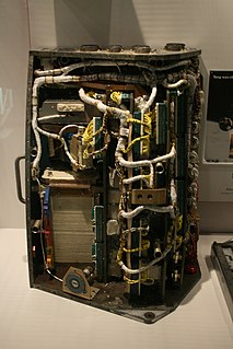
The IBM System/4 Pi is a family of avionics computers used, in various versions, on the F-15 Eagle fighter, E-3 Sentry AWACS, Harpoon Missile, NASA's Skylab, MOL, and the Space Shuttle, as well as other aircraft. The name of the system refers to the number of steradians (4π) in a sphere. Development began in 1965, deliveries in 1967.

Several planned missions of the Apollo crewed Moon landing program of the 1960s and 1970s were canceled for a variety of reasons, including changes in technical direction, the Apollo 1 fire, hardware delays, and budget limitations. After the landing by Apollo 12, Apollo 20, which would have been the final crewed mission to the Moon, was canceled to allow Skylab to launch as a "dry workshop". The next two missions, Apollos 18 and 19, were later canceled after the Apollo 13 incident and further budget cuts. Two Skylab missions also ended up being canceled. Two complete Saturn Vs ended up going unused and are currently on display in the United States.

The Saturn C-4 was the fourth rocket in the Saturn C series studied from 1959 to 1962. The C-4 design was proposed in 1960 for a three-stage launch vehicle that could launch 99,000 kg (218,000 lb) to Low Earth orbit and send 32,000 kg (70,000 lb) to the Moon via Trans-lunar injection. It met the initial requirements for a lunar orbit rendezvous and lunar landing mission.

ST-124-M3 inertial platform navigational instrument on the Apollo V launch vehicle

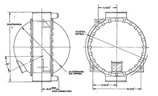
The ST-124-M3 inertial platform was a device for measuring acceleration and attitude of the Saturn V launch vehicle. It was carried by the Saturn V Instrument Unit, a 3-foot-high (0.91 m), 22-foot-diameter (6.7 m) section of the Saturn V that fit between the third stage (S-IVB) and the Apollo spacecraft. Its nomenclature means "stable table" (ST) for use in the moon mission (M), and it has 3 gimbals.

Saturn V dynamic test vehicle United States historic place

The Saturn V dynamic test vehicle, designated SA-500D, is a prototype Saturn V rocket used by NASA to test the performance of the rocket when vibrated to simulate the shaking which subsequent rockets would experience during launch. It was the first full-scale Saturn V completed by the Marshall Space Flight Center (MSFC). Though SA-500D never flew, it was instrumental in the development of the Saturn V rocket which propelled the first men to the Moon as part of the Apollo program. Built under the direction of Dr. Wernher von Braun, it served as the test vehicle for all of the Saturn support facilities at MSFC.

Saturn V American expendable rocket

Saturn V was an American human-rated super heavy-lift launch vehicle used by NASA between 1967 and 1973. The three-stage liquid-propellant expendable rocket was developed to support the Apollo program for human exploration of the Moon and was later used to launch Skylab, the first American space station.

ASC-15 digital computer for the Titan II

The ASC-15 was a digital computer developed by International Business Machines (IBM) for use on the Titan II intercontinental ballistic missile (ICBM). It was subsequently modified and used on the Titan III and Saturn I Block II launch vehicles.

Walter Haeussermann German-American aerospace engineer

Walter Haeussermann was a German-American aerospace engineer and member of the "von Braun rocket group", both at Peenemünde and later at Marshall Space Flight Center, where he was the director of the guidance and control laboratory. He was awarded the Department of the Army Decoration for Exceptional Civilian Service in 1959 for his contributions to the US rocket program.

Gemini Guidance Computer digital computer designed for Project Gemini

The Gemini Guidance Computer was a digital, serial computer designed for Project Gemini, America's second manned space project. The computer, which facilitated the control of mission maneuvers, was designed by the IBM Federal Systems Division.

In computing, a syllable is a name for a platform-dependent unit of information storage. Depending on the target hardware, various bit widths are associated with it. Commonly used in the 1960s and 1970s, the term has mostly fallen into disuse in favour of terms like byte or word.

References

Notes

  1. Burkey, Ronald (2009-08-21). "Virtual AGC — AGS — LVDC — Gemini: Launch Vehicle Digital Computer (LVDC): Saturn IB and Saturn V Rockets". Latest version of this site is on ibiblio. Archived from the original on 2016-05-28. Retrieved 2016-05-28.
  2. Saturn Launch Vehicles TR X-881
  3. Haeussermann 1970, pp. 30-31.
  4. Apollo Study Report, Volume 2, pages 3-36 to 3-37. The log book for the LVDC at National Air and Space Museum says the dimensions were 31x13.1x13 inches and the weight was 90 pounds.
  5. 1 2 3 M.M. Dickinson, J.B. Jackson, G.C. Randa. IBM Space Guidance Center, Owego, NY. "Saturn V Launch Vehicle Digital Computer and Data Adapter." Proceedings of the Fall Joint Computer Conference, 1964
  6. Apollo Study Report, Volume 2, page 3-4.
  7. Apollo Study Report, Volume 2, page 2-37
  8. Haeussermann 1970, pp. 23.
  9. Pugh, Emerson; Johnson; Palmer, John (1991). IBM's 360 and Early 370 Systems . MIT Press. p.  108. ISBN   978-0262161237.