Related Research Articles

The Intel 8080 ("eighty-eighty") is the second 8-bit microprocessor designed and manufactured by Intel. It first appeared in April 1974 and is an extended and enhanced variant of the earlier 8008 design, although without binary compatibility. Although earlier microprocessors were commonly used in mass-produced devices such as calculators, cash registers, computer terminals, industrial robots, and other applications, the 8080 saw greater success in a wider set of applications, and is largely credited with starting the microcomputer industry.

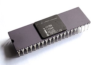
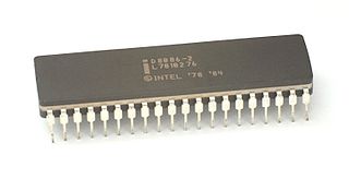
The 8086 is a 16-bit microprocessor chip designed by Intel between early 1976 and June 8, 1978, when it was released. The Intel 8088, released July 1, 1979, is a slightly modified chip with an external 8-bit data bus, and is notable as the processor used in the original IBM PC design.

x86 is a family of complex instruction set computer (CISC) instruction set architectures initially developed by Intel based on the 8086 microprocessor and its 8-bit-external-bus variant, the 8088. The 8086 was introduced in 1978 as a fully 16-bit extension of 8-bit Intel's 8080 microprocessor, with memory segmentation as a solution for addressing more memory than can be covered by a plain 16-bit address. The term "x86" came into being because the names of several successors to Intel's 8086 processor end in "86", including the 80186, 80286, 80386 and 80486. Colloquially, their names were "186", "286", "386" and "486".
In computer science, threaded code is a programming technique where the code has a form that essentially consists entirely of calls to subroutines. It is often used in compilers, which may generate code in that form or be implemented in that form themselves. The code may be processed by an interpreter or it may simply be a sequence of machine code call instructions.
In computer science, an instruction set architecture (ISA) is an abstract model that generally defines how software controls the CPU in a computer or a family of computers. A device or program that executes instructions described by that ISA, such as a central processing unit (CPU), is called an implementation of that ISA.

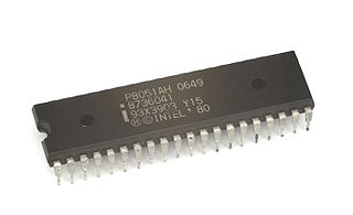
The Intel MCS-51 is a single chip microcontroller (MCU) series developed by Intel in 1980 for use in embedded systems. The architect of the Intel MCS-51 instruction set was John H. Wharton. Intel's original versions were popular in the 1980s and early 1990s, and enhanced binary compatible derivatives remain popular today. It is a complex instruction set computer with separate memory spaces for program instructions and data.
The Intel x86 computer instruction set architecture has supported memory segmentation since the original Intel 8086 in 1978. It allows programs to address more than 64 KB (65,536 bytes) of memory, the limit in earlier 80xx processors. In 1982, the Intel 80286 added support for virtual memory and memory protection; the original mode was renamed real mode, and the new version was named protected mode. The x86-64 architecture, introduced in 2003, has largely dropped support for segmentation in 64-bit mode.
x86 assembly language is the name for the family of assembly languages which provide some level of backward compatibility with CPUs back to the Intel 8008 microprocessor, which was launched in April 1972. It is used to produce object code for the x86 class of processors.

An index register in a computer's CPU is a processor register used for pointing to operand addresses during the run of a program. It is useful for stepping through strings and arrays. It can also be used for holding loop iterations and counters. In some architectures it is used for read/writing blocks of memory. Depending on the architecture it may be a dedicated index register or a general-purpose register. Some instruction sets allow more than one index register to be used; in that case additional instruction fields may specify which index registers to use.
Fetching the instruction opcodes from program memory well in advance is known as prefetching and it is served by using a prefetch input queue (PIQ). The pre-fetched instructions are stored in a queue. The fetching of opcodes well in advance, prior to their need for execution, increases the overall efficiency of the processor boosting its speed. The processor no longer has to wait for the memory access operations for the subsequent instruction opcode to complete. This architecture was prominently used in the Intel 8086 microprocessor.
The x86 instruction set refers to the set of instructions that x86-compatible microprocessors support. The instructions are usually part of an executable program, often stored as a computer file and executed on the processor.
Addressing modes are an aspect of the instruction set architecture in most central processing unit (CPU) designs. The various addressing modes that are defined in a given instruction set architecture define how the machine language instructions in that architecture identify the operand(s) of each instruction. An addressing mode specifies how to calculate the effective memory address of an operand by using information held in registers and/or constants contained within a machine instruction or elsewhere.
In computer engineering, an orthogonal instruction set is an instruction set architecture where all instruction types can use all addressing modes. It is "orthogonal" in the sense that the instruction type and the addressing mode may vary independently. An orthogonal instruction set does not impose a limitation that requires a certain instruction to use a specific register so there is little overlapping of instruction functionality.
In computing, the reset vector is the default location a central processing unit will go to find the first instruction it will execute after a reset. The reset vector is a pointer or address, where the CPU should always begin as soon as it is able to execute instructions. The address is in a section of non-volatile memory initialized to contain instructions to start the operation of the CPU, as the first step in the process of booting the system containing the CPU.
In computing, the x86 memory models are a set of six different memory models of the x86 CPU operating in real mode which control how the segment registers are used and the default size of pointers.
A Trace Vector Decoder (TVD) is computer software that uses the trace facility of its underlying microprocessor to decode encrypted instruction opcodes just-in-time prior to execution and possibly re-encode them afterwards. It can be used to hinder reverse engineering when attempting to prevent software cracking as part of an overall copy protection strategy.
The FLAGS register is the status register that contains the current state of an x86 CPU. The size and meanings of the flag bits are architecture dependent. It usually reflects the result of arithmetic operations as well as information about restrictions placed on the CPU operation at the current time. Some of those restrictions may include preventing some interrupts from triggering, prohibition of execution of a class of "privileged" instructions. Additional status flags may bypass memory mapping and define what action the CPU should take on arithmetic overflow.
This article describes the calling conventions used when programming x86 architecture microprocessors.
A trap flag permits operation of a processor in single-step mode. If such a flag is available, debuggers can use it to step through the execution of a computer program.
The PDP-11 architecture is a 16-bit CISC instruction set architecture (ISA) developed by Digital Equipment Corporation (DEC). It is implemented by central processing units (CPUs) and microprocessors used in PDP-11 minicomputers. It was in wide use during the 1970s, but was eventually overshadowed by the more powerful VAX architecture in the 1980s.
References
- ↑ Salomon, David (February 1993) [1992]. Written at California State University, Northridge, California, USA. Chivers, Ian D. (ed.). Assemblers and Loaders (PDF). Ellis Horwood Series In Computers And Their Applications (1 ed.). Chicester, West Sussex, UK: Ellis Horwood Limited / Simon & Schuster International Group. ISBN 0-13-052564-2. Archived (PDF) from the original on 2020-03-23. Retrieved 2008-10-01.
Most computers save the return address in either the stack, in one of the registers, or in the first word of the procedure (in which case the first executable instruction of the procedure should be stored in the second word). If the latter method is used, a return from the procedure is a jump to the memory location whose address is contained in the first word of the procedure.
(xiv+294+4 pages) - ↑ Howard, Brian. "Assembly Tutorial - Instructions". Computer Science Department, DePauw University. Retrieved 2013-07-19.
- ↑ Stokes, Jon "Hannibal" (2004-02-25). "A Look at Centrino's Core: The Pentium M". archive.arstechnica.com. p. 5.
- 1 2 Fog, Agner. "The microarchitecture of Intel, AMD and VIA CPUs" (PDF). Technical University of Denmark.