EMF measurement

Last updated
Electric field probe FP2000 (range 100 kHz - 2137 MHz) Clampco Sistemi Efield probe FP2000.jpg
Electric field probe FP2000 (range 100 kHz – 2137 MHz)

EMF measurements are measurements of ambient (surrounding) electromagnetic fields that are performed using particular sensors or probes, such as EMF meters. These probes can be generally considered as antennas although with different characteristics. In fact, probes should not perturb the electromagnetic field and must prevent coupling and reflection as much as possible in order to obtain precise results. There are two main types of EMF measurements:

Contents

EMF probes may respond to fields only on one axis, or may be tri-axial, showing components of the field in three directions at once. Amplified, active, probes can improve measurement precision and sensitivity but their active components may limit their speed of response.

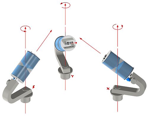
Ideal isotropic measurements

E-field projections on an orthogonal reference frame E field reconstruction.png
E-field projections on an orthogonal reference frame

Measurements of the EMF are obtained using an E-field sensor or H-field sensor which can be isotropic or mono-axial, active or passive. A mono-axial, omnidirectional probe is a device which senses the Electric (short dipole) or Magnetic field linearly polarized in a given direction.

Using a mono-axial probe implies the need for three measurements taken with the sensor axis set up along three mutually orthogonal directions, in a X, Y, Z configuration. As an example, it can be used as a probe which senses the Electric field component parallel to the direction of its axis of symmetry. In these conditions, where E is the amplitude of incident electric field, and θ is the amplitude of the angle between sensor axis and direction of electric field E, the signal detected is proportional to |E|cos θ (right). This allows obtainment of the correct total amplitude of the field in the form of

or, in case of the magnetic field

An isotropic (tri-axial) probe simplifies the measurement procedure because the total field value is determined with three measures taken without changing sensor position: this results from the geometry of the device which is made by three independent broadband sensing elements placed orthogonal to each other. In practice, each element's output is measured in three consecutive time intervals supposing field components being time stationary .

Clampco Sistemi xyz conf FP2000.jpg
Isotropic antenna AT3000 (passive probe, 20 MHz - 3000 MHz) Clampco Sistemi Isotropic antenna AT3000.jpg
Isotropic antenna AT3000 (passive probe, 20 MHz – 3000 MHz)

Meters

An EMF meter is a scientific instrument for measuring electromagnetic fields (abbreviated as EMF). Most meters measure the electromagnetic radiation flux density (DC fields) or the change in an electromagnetic field over time (AC fields), essentially the same as a radio antenna, but with quite different detection characteristics.

The two largest categories are single axis and tri-axis. Single axis meters are cheaper than tri-axis meters, but take longer to complete a survey because the meter only measures one dimension of the field. Single axis instruments have to be tilted and turned on all three axes to obtain a full measurement. A tri-axis meter measures all three axes simultaneously, but these models tend to be more expensive.

Electromagnetic fields can be generated by AC current or DC currents. An EMF meter can measure AC electromagnetic fields, which are usually emitted from man-made sources such as electrical wiring, while gaussmeters or magnetometers measure DC fields, which occur naturally in Earth's geomagnetic field and are emitted from other sources where direct current is present.

An example of an EMF meter. Ext trifield3axisuhsmeter.jpg
An example of an EMF meter.

Sensitivity and Calibration

As most electromagnetic fields encountered in everyday situations are those generated by household or industrial appliances, the majority of EMF meters available are calibrated to measure 50 and 60  Hz alternating fields (the frequency of European and US mains electricity). There are other meters which can measure fields alternating at as low as 20 Hz, however these tend to be much more expensive and are only used for specific research purposes.

Active and passive sensors

Active sensors are sensing devices which contain active components; usually this solution allows for a more precise measurement with respect to passive components. In fact, a passive receiving antenna collects energy from the electromagnetic field being measured and makes it available at a RF cable connector. This signal then goes to the spectrum analyzer but the field characteristics can be someway modified by the presence of the cable, especially in near-field conditions.

On the other hand, an effective solution is to transfer on an optical carrier, the electric (or magnetic) field component sensed with an active probe. The basic components of the system are a receiving electro-optical antenna which is able to transfer, on an optical carrier, the individual electric (or magnetic) field component picked up and to return it in the form of an electrical signal at the output port of an opto-electric converter.

Optical modulation.gif

The modulated optical carrier is transferred by means of a fiber-optic link to a converter which extracts the modulating signal and converts it back to an electrical signal. The electrical signal thus obtained can be then sent to a spectrum analyzer with a 50 Ω common RF cable.

Isotropic deviation

Short dipole radiation pattern Short dipole radiation pattern.gif
Short dipole radiation pattern

Isotropic deviation, in EMF measurements, is a parameter that describes the accuracy in measuring field intensities irrespective of the probe's orientation. If the field is obtained by three measurements in an orthogonal X, Y, Z configuration in the form:

a sufficient condition for the expression to be true for every three orthogonal coordinates (X,Y,Z) is for the probe radiation pattern to be as close as possible to ideal short dipole pattern, called sin θ:

where A is function of frequency. The difference between ideal dipole radiation pattern and real probe pattern is called isotropic deviation.

Related Research Articles

<span class="mw-page-title-main">Fresnel equations</span> Equations of light transmission and reflection

The Fresnel equations describe the reflection and transmission of light when incident on an interface between different optical media. They were deduced by French engineer and physicist Augustin-Jean Fresnel who was the first to understand that light is a transverse wave, when no one realized that the waves were electric and magnetic fields. For the first time, polarization could be understood quantitatively, as Fresnel's equations correctly predicted the differing behaviour of waves of the s and p polarizations incident upon a material interface.

<span class="mw-page-title-main">Circular polarization</span> Polarization state

In electrodynamics, circular polarization of an electromagnetic wave is a polarization state in which, at each point, the electromagnetic field of the wave has a constant magnitude and is rotating at a constant rate in a plane perpendicular to the direction of the wave.

A magneto-optic effect is any one of a number of phenomena in which an electromagnetic wave propagates through a medium that has been altered by the presence of a quasistatic magnetic field. In such a medium, which is also called gyrotropic or gyromagnetic, left- and right-rotating elliptical polarizations can propagate at different speeds, leading to a number of important phenomena. When light is transmitted through a layer of magneto-optic material, the result is called the Faraday effect: the plane of polarization can be rotated, forming a Faraday rotator. The results of reflection from a magneto-optic material are known as the magneto-optic Kerr effect.

<span class="mw-page-title-main">Polarization (waves)</span> Property of waves that can oscillate with more than one orientation

Polarization is a property of transverse waves which specifies the geometrical orientation of the oscillations. In a transverse wave, the direction of the oscillation is perpendicular to the direction of motion of the wave. A simple example of a polarized transverse wave is vibrations traveling along a taut string (see image); for example, in a musical instrument like a guitar string. Depending on how the string is plucked, the vibrations can be in a vertical direction, horizontal direction, or at any angle perpendicular to the string. In contrast, in longitudinal waves, such as sound waves in a liquid or gas, the displacement of the particles in the oscillation is always in the direction of propagation, so these waves do not exhibit polarization. Transverse waves that exhibit polarization include electromagnetic waves such as light and radio waves, gravitational waves, and transverse sound waves in solids.

<span class="mw-page-title-main">Magnetometer</span> Device that measures magnetism

A magnetometer is a device that measures magnetic field or magnetic dipole moment. Different types of magnetometers measure the direction, strength, or relative change of a magnetic field at a particular location. A compass is one such device, one that measures the direction of an ambient magnetic field, in this case, the Earth's magnetic field. Other magnetometers measure the magnetic dipole moment of a magnetic material such as a ferromagnet, for example by recording the effect of this magnetic dipole on the induced current in a coil.

In electromagnetics, an evanescent field, or evanescent wave, is an oscillating electric and/or magnetic field that does not propagate as an electromagnetic wave but whose energy is spatially concentrated in the vicinity of the source. Even when there is a propagating electromagnetic wave produced, one can still identify as an evanescent field the component of the electric or magnetic field that cannot be attributed to the propagating wave observed at a distance of many wavelengths.

This is an index of articles relating to electronics and electricity or natural electricity and things that run on electricity and things that use or conduct electricity.

Fourier optics is the study of classical optics using Fourier transforms (FTs), in which the waveform being considered is regarded as made up of a combination, or superposition, of plane waves. It has some parallels to the Huygens–Fresnel principle, in which the wavefront is regarded as being made up of a combination of spherical wavefronts whose sum is the wavefront being studied. A key difference is that Fourier optics considers the plane waves to be natural modes of the propagation medium, as opposed to Huygens–Fresnel, where the spherical waves originate in the physical medium.

<span class="mw-page-title-main">Time of flight</span> Timing of substance within a medium

Time of flight (ToF) is the measurement of the time taken by an object, particle or wave to travel a distance through a medium. This information can then be used to measure velocity or path length, or as a way to learn about the particle or medium's properties. The traveling object may be detected directly or indirectly. Time of flight technology has found valuable applications in the monitoring and characterization of material and biomaterials, hydrogels included.

The Faraday effect or Faraday rotation, sometimes referred to as the magneto-optic Faraday effect (MOFE), is a physical magneto-optical phenomenon. The Faraday effect causes a polarization rotation which is proportional to the projection of the magnetic field along the direction of the light propagation. Formally, it is a special case of gyroelectromagnetism obtained when the dielectric permittivity tensor is diagonal. This effect occurs in most optically transparent dielectric materials under the influence of magnetic fields.

<span class="mw-page-title-main">Radar cross section</span> Strength of an objects radar echo

Radar cross-section (RCS), denoted σ, also called radar signature, is a measure of how detectable an object is by radar. A larger RCS indicates that an object is more easily detected.

<span class="mw-page-title-main">Isotropic radiator</span>

An isotropic radiator is a theoretical point source of electromagnetic or sound waves which radiates the same intensity of radiation in all directions. It has no preferred direction of radiation. It radiates uniformly in all directions over a sphere centred on the source. Isotropic radiators are used as reference radiators with which other sources are compared, for example in determining the gain of antennas. A coherent isotropic radiator of electromagnetic waves is theoretically impossible, but incoherent radiators can be built. An isotropic sound radiator is possible because sound is a longitudinal wave.

Antenna measurement techniques refers to the testing of antennas to ensure that the antenna meets specifications or simply to characterize it. Typical parameters of antennas are gain, bandwidth, radiation pattern, beamwidth, polarization, and impedance.

<span class="mw-page-title-main">Directivity</span> Measure of how much of an antennas signal is transmitted in one direction

In electromagnetics, directivity is a parameter of an antenna or optical system which measures the degree to which the radiation emitted is concentrated in a single direction. It is the ratio of the radiation intensity in a given direction from the antenna to the radiation intensity averaged over all directions. Therefore, the directivity of a hypothetical isotropic radiator is 1, or 0 dBi.

<span class="mw-page-title-main">C/NOFS</span>

C/NOFS, or Communications/Navigation Outage Forecasting System was a USAF satellite developed by the Air Force Research Laboratory (AFRL) Space Vehicles Directorate to investigate and forecast scintillations in the Earth's ionosphere. It was launched by an Orbital Sciences Corporation Pegasus-XL launch vehicle at 17:02:48 UTC on 16 April 2008 and decayed on 28 November 2015.

Spacecraft attitude control is the process of controlling the orientation of a spacecraft with respect to an inertial frame of reference or another entity such as the celestial sphere, certain fields, and nearby objects, etc.

A vector measuring current meter (VMCM) is an instrument used for obtaining measurements of horizontal velocity in the upper ocean, which exploits two orthogonal cosine response propeller sensors that directly measure the components of horizontal velocity. VMCM was developed in the late 1970s by Drs. Robert Weller and Russ Davis and commercially produced by EG&G Sealink System . The instrument has the capability of one year long deployment at depths of up to 5000 m. Both laboratory and field test results show that the VMCM is capable of making accurate measurements of horizontal velocity in the upper ocean. The VMCM is the current standard for making high quality velocity measurements in near-surface regions and it has been used for benchmarking other current meters.

<span class="mw-page-title-main">Slotted line</span> Device used for microwave measurements

Slotted lines are used for microwave measurements and consist of a movable probe inserted into a slot in a transmission line. They are used in conjunction with a microwave power source and usually, in keeping with their low-cost application, a low cost Schottky diode detector and VSWR meter rather than an expensive microwave power meter.

<span class="mw-page-title-main">Anisotropic terahertz microspectroscopy</span> Spectroscopic technique

Anisotropic terahertz microspectroscopy (ATM) is a spectroscopic technique in which molecular vibrations in an anisotropic material are probed with short pulses of terahertz radiation whose electric field is linearly polarized parallel to the surface of the material. The technique has been demonstrated in studies involving single crystal sucrose, fructose, oxalic acid, and molecular protein crystals in which the spatial orientation of molecular vibrations are of interest.

References

    Bibliography