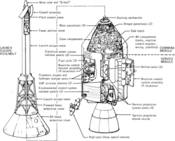
The Apollo command and service module (CSM) was one of two principal components of the United States Apollo spacecraft, used for the Apollo program, which landed astronauts on the Moon between 1969 and 1972. The CSM functioned as a mother ship, which carried a crew of three astronauts and the second Apollo spacecraft, the Apollo Lunar Module, to lunar orbit, and brought the astronauts back to Earth. It consisted of two parts: the conical command module, a cabin that housed the crew and carried equipment needed for atmospheric reentry and splashdown; and the cylindrical service module which provided propulsion, electrical power and storage for various consumables required during a mission. An umbilical connection transferred power and consumables between the two modules. Just before reentry of the command module on the return home, the umbilical connection was severed and the service module was cast off and allowed to burn up in the atmosphere.
The CSM was developed and built for NASA by North American Aviation starting in November 1961. It was initially designed to land on the Moon atop a landing rocket stage and return all three astronauts on a direct-ascent mission, which would not use a separate lunar module, and thus had no provisions for docking with another spacecraft. This, plus other required design changes, led to the decision to design two versions of the CSM: Block I was to be used for uncrewed missions and a single crewed Earth orbit flight (Apollo 1), while the more advanced Block II was designed for use with the lunar module. The Apollo 1 flight was cancelled after a cabin fire killed the crew and destroyed their command module during a launch rehearsal test. Corrections of the problems which caused the fire were applied to the Block II spacecraft, which was used for all crewed spaceflights.
Nineteen CSMs were launched into space. Of these, nine flew humans to the Moon between 1968 and 1972, and another two performed crewed test flights in low Earth orbit, all as part of the Apollo program. Before these, another four CSMs had flown as uncrewed Apollo tests, of which two were suborbital flights and another two were orbital flights. Following the conclusion of the Apollo program and during 1973–1974, three CSMs ferried astronauts to the orbital Skylab space station. Finally in 1975, the last flown CSM docked with the Soviet craft Soyuz 19 as part of the international Apollo–Soyuz Test Project.
Before Apollo
Concepts of an advanced crewed spacecraft started before the Moon landing goal was announced. The three-person vehicle was to be mainly for orbital use around Earth. It would include a large pressurized auxiliary orbital module where the crew would live and work for weeks at a time. They would perform space station-type activities in the module, while later versions would use the module to carry cargo to space stations. The spacecraft was to service the Project Olympus (LORL), a foldable rotating space station launched on a single Saturn V. Later versions would be used on circumlunar flights, and would be the basis for a direct ascent lunar spacecraft as well as used on interplanetary missions. In late 1960, NASA called on U.S. industry to propose designs for the vehicle. On May 25, 1961 President John F. Kennedy announced the Moon landing goal before 1970, which immediately rendered NASA's Olympus Station plans obsolete.[2][3]
Development history
Moon Mission (1967) Official NASA Apollo Program information film reel.
When NASA awarded the initial Apollo contract to North American Aviation on November 28, 1961, it was still assumed the lunar landing would be achieved by direct ascent rather than by lunar orbit rendezvous.[4] Therefore, design proceeded without a means of docking the command module to a lunar excursion module (LEM). But the change to lunar orbit rendezvous, plus several technical obstacles encountered in some subsystems (such as environmental control), soon made it clear that substantial redesign would be required. In 1963, NASA decided the most efficient way to keep the program on track was to proceed with the development in two versions:[5]
Block I would continue the preliminary design, to be used for early low Earth orbit test flights only.
Block II would be the lunar-capable version, including a docking hatch and incorporating weight reduction and lessons learned in Block I. Detailed design of the docking capability depended on design of the LEM, which was contracted to Grumman Aircraft Engineering.
By January 1964, North American started presenting Block II design details to NASA.[6] Block I spacecraft were used for all uncrewed Saturn 1B and Saturn V test flights. Initially two crewed flights were planned, but this was reduced to one in late 1966. This mission, designated AS-204 but named Apollo 1 by its flight crew, was planned for launch on February 21, 1967. During a dress rehearsal for the launch on January 27, all three astronauts (Gus Grissom, Ed White and Roger Chaffee) were killed in a cabin fire, which revealed serious design, construction and maintenance shortcomings in Block I, many of which had been carried over into Block II command modules being built at the time.[citation needed]
After a thorough investigation by the Apollo 204 Review Board, it was decided to terminate the crewed Block I phase and redefine Block II to incorporate the review board's recommendations. Block II incorporated a revised CM heat shield design, which was tested on the uncrewed Apollo 4 and Apollo 6 flights, so the first all-up Block II spacecraft flew on the first crewed mission, Apollo 7.[citation needed]
The two blocks were essentially similar in overall dimensions, but several design improvements resulted in weight reduction in Block II. Also, the Block I service module propellant tanks were slightly larger than in Block II. The Apollo 1 spacecraft weighed approximately 45,000 pounds (20,000kg), while the Block II Apollo 7 weighed 36,400lb (16,500kg). (These two Earth orbital craft were lighter than the craft which later went to the Moon, as they carried propellant in only one set of tanks, and did not carry the high-gain S-band antenna.) In the specifications given below, unless otherwise noted, all weights given are for the Block II spacecraft.[citation needed]
The total cost of the CSM for development and the units produced was $36.9billion in 2016 dollars, adjusted from a nominal total of $3.7billion[7] using the NASA New Start Inflation Indices.[8]
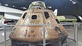
Command module (CM)
Command module interior arrangement
The command module was a truncated cone (frustum) with a diameter of 12feet 10inches (3.91m) across the base, and a height of 11feet 5inches (3.48m) including the docking probe and dish-shaped aft heat shield. The forward compartment contained two reaction control system thrusters, the docking tunnel, and the Earth Landing System. The inner pressure vessel housed the crew accommodation, equipment bays, controls and displays, and many spacecraft systems. The aft compartment contained 10 reaction control engines and their related propellant tanks, freshwater tanks, and the CSM umbilical cables.[9]
Construction
The command module was built in North American's factory in Downey, California,[10][11] and consisted of two basic structures joined together: the inner structure (pressure shell) and the outer structure.[citation needed]
The inner structure was an aluminum sandwich construction consisting of a welded aluminum inner skin, adhesively bonded aluminum honeycomb core, and outer face sheet. The thickness of the honeycomb varied from about 1.5 inches (3.8cm) at the base to about 0.25 inches (0.64cm) at the forward access tunnel. This inner structure was the pressurized crew compartment.[citation needed]
The outer structure was made of stainless steel brazed-honeycomb brazed between steel alloy face sheets. It varied in thickness from 0.5 inch to 2.5 inches. Part of the area between the inner and outer shells was filled with a layer of fiberglass insulation as additional heat protection.[12]
Thermal protection (heat shield)
Command module reentering the atmosphere at a non-zero angle of attack in order to establish a lifting entry and control the landing site (artistic rendition)
An ablative heat shield on the outside of the CM protected the capsule from the heat of reentry, which is sufficient to melt most metals. This heat shield was composed of phenolic formaldehyde resin. During reentry, this material charred and melted away, absorbing and carrying away the intense heat in the process. The heat shield has several outer coverings: a pore seal, a moisture barrier (a white reflective coating), and a silver Mylar thermal coating that looks like aluminum foil.[citation needed]
The heat shield varied in thickness from 2 inches (5.1cm) in the aft portion (the base of the capsule, which faced forward during reentry) to 0.5 inches (1.3cm) in the crew compartment and forward portions. The total weight of the shield was about 3,000 pounds (1,400kg).[12]
Forward compartment
The 1-foot-11-inch (0.58m)-tall forward compartment was the area outside the inner pressure shell in the nose of the capsule, located around the forward docking tunnel and covered by the forward heat shield. The compartment was divided into four 90-degree segments that contained Earth landing equipment (all the parachutes, recovery antennas and beacon light, and sea recovery sling), two reaction control thrusters, and the forward heat shield release mechanism.[citation needed]
At about 25,000 feet (7,600m) during reentry, the forward heat shield was jettisoned to expose the Earth landing equipment and permit deployment of the parachutes.[12]
Aft compartment
The 1-foot-8-inch (0.51m)-tall aft compartment was located around the periphery of the command module at its widest part, just forward of (above) the aft heat shield. The compartment was divided into 24 bays containing 10 reaction control engines; the fuel, oxidizer, and helium tanks for the CM reaction control subsystem; water tanks; the crushable ribs of the impact attenuation system; and a number of instruments. The CM-SM umbilical, the point where wiring and plumbing ran from one module to the other, was also in the aft compartment. The panels of the heat shield covering the aft compartment were removable for maintenance of the equipment before flight.[12]
Earth landing system
The Apollo 15 Command Module splashes down in the Pacific Ocean, 1971. Scale model of the Apollo command and service module at the Euro Space Center in Belgium
The components of the ELS were housed around the forward docking tunnel. The forward compartment was separated from the central by a bulkhead and was divided into four 90-degree wedges. The ELS consisted of two drogue parachutes with mortars, three main parachutes, three pilot parachutes to deploy the mains, three inflation bags for uprighting the capsule if necessary, a sea recovery cable, a dye marker, and a swimmer umbilical.[citation needed]
The command module's center of mass was offset a foot or so from the center of pressure (along the symmetry axis). This provided a rotational moment during reentry, angling the capsule and providing some lift (a lift to drag ratio of about 0.368).[13] The capsule was then steered by rotating the capsule using thrusters; when no steering was required, the capsule was spun slowly, and the lift effects cancelled out. This system greatly reduced the g-force experienced by the astronauts, permitted a reasonable amount of directional control and allowed the capsule's splashdown point to be targeted within a few miles.[citation needed]
At 24,000 feet (7,300m), the forward heat shield was jettisoned using four pressurized-gas compression springs. The drogue parachutes were then deployed, slowing the spacecraft to 125 miles per hour (201 kilometres per hour). At 10,700 feet (3,300m) the drogues were jettisoned and the pilot parachutes, which pulled out the mains, were deployed. These slowed the CM to 22 miles per hour (35 kilometres per hour) for splashdown. The portion of the capsule that first contacted the water surface contained four crushable ribs to further mitigate the force of impact. The command module could safely parachute to an ocean landing with only two parachutes deployed (as occurred on Apollo 15), the third parachute being a safety precaution.[citation needed]
Reaction control system
The command module attitude control system consisted of twelve 93-pound-force (410N) attitude control thrusters, ten of which were located in the aft compartment, plus two in the forward compartment. These were supplied by four tanks storing 270 pounds (120kg) of monomethylhydrazine fuel and nitrogen tetroxide oxidizer, and pressurized by 1.1 pounds (0.50kg) of helium stored at 4,150 pounds per square inch (28.6MPa) in two tanks.[citation needed]
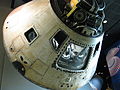
Hatches
The forward docking hatch was mounted at the top of the docking tunnel. It was 30 inches (76cm) in diameter and weighed 80 pounds (36kg), constructed from two machined rings that were weld-joined to a brazed honeycomb panel. The exterior side was covered with 0.5-inch (13mm) of insulation and a layer of aluminum foil. It was latched in six places and operated by a pump handle. The hatch contained a valve in its center, used to equalize the pressure between the tunnel and the CM so the hatch could be removed.[citation needed]
The unified crew hatch (UCH) measured 29 inches (74cm) high, 34 inches (86cm) wide, and weighed 225 pounds (102kg). It was operated by a pump handle, which drove a ratchet mechanism to open or close fifteen latches simultaneously.[citation needed]
Docking assembly
Apollo's mission required the LM to dock with the CSM on return from the Moon, and also in the transposition, docking, and extraction maneuver at the beginning of the translunar coast. The docking mechanism was a non-androgynous system, consisting of a probe located in the nose of the CSM, which connected to the drogue, a truncated cone located on the lunar module. The probe was extended like a scissor jack to capture the drogue on initial contact, known as soft docking. Then the probe was retracted to pull the vehicles together and establish a firm connection, known as "hard docking". The mechanism was specified by NASA to have the following functions:[citation needed]
Allow the two vehicles to connect, and attenuate excess movement and energy caused by docking
Align and center the two vehicles and pull them together for capture
Provide a rigid structural connection between both vehicles, and be capable of removal and re-installation by a single crewman
Provide a means of remote separation of both vehicles for the return to Earth, using pyrotechnic fasteners at the circumference of the CSM docking collar
Provide redundant power and logic circuits for all electrical and pyrotechnic components.[citation needed]
Coupling
The probe head located in the CSM was self-centering and gimbal-mounted to the probe piston. As the probe head engaged in the opening of the drogue socket, three spring-loaded latches depressed and engaged. These latches allowed a so-called 'soft dock' state and enabled the pitch and yaw movements in the two vehicles to subside. Excess movement in the vehicles during the 'hard dock' process could cause damage to the docking ring and put stress on the upper tunnel. A depressed locking trigger link at each latch allowed a spring-loaded spool to move forward, maintaining the toggle linkage in an over-center locked position. In the upper end of the lunar module tunnel, the drogue, which was constructed of 1-inch-thick aluminum honeycomb core, bonded front and back to aluminum face sheets, was the receiving end of the probe head capture latches.[citation needed]
Retraction
After the initial capture and stabilization of the vehicles, the probe was capable of exerting a closing force of 1,000 pounds-force (4.4kN) to draw the vehicles together. This force was generated by gas pressure acting on the center piston within the probe cylinder. Piston retraction compressed the probe and interface seals and actuated the 12 automatic ring latches which were located radially around the inner surface of the CSM docking ring. The latches were manually re-cocked in the docking tunnel by an astronaut after each hard docking event (lunar missions required two dockings).[citation needed]
Separation
An automatic extension latch attached to the probe cylinder body engaged and retained the probe center piston in the retracted position. Before vehicle separation in lunar orbit, manual cocking of the twelve ring latches was accomplished. The separating force from the internal pressure in the tunnel area was then transmitted from the ring latches to the probe and drogue. In undocking, the release of the capture latches was accomplished by electrically energizing tandem-mounted DC rotary solenoids located in the center piston. In a temperature degraded condition, a single motor release operation was done manually in the lunar module by depressing the locking spool through an open hole in the probe heads, while release from the CSM was done by rotating a release handle at the back of the probe to rotate the motor torque shaft manually.[14] When the command and lunar modules separated for the last time, the probe and forward docking ring were pyrotechnically separated, leaving all docking equipment attached to the lunar module. In the event of an abort during launch from Earth, the same system would have explosively jettisoned the docking ring and probe from the CM as it separated from the boost protective cover.[citation needed]
Cabin interior arrangement
Main control panelOriginal cockpit of the command module of Apollo 11 with three seats, photographed from above. It is located in the National Air and Space Museum, the very high resolution image was produced in 2007 by the Smithsonian Institution.
The central pressure vessel of the command module was its sole habitable compartment. It had an interior volume of 210 cubic feet (5.9m3) and housed the main control panels, crew seats, guidance and navigation systems, food and equipment lockers, the waste management system, and the docking tunnel.
Dominating the forward section of the cabin was the crescent-shaped main display panel measuring nearly 7 feet (2.1m) wide and 3 feet (0.91m) tall. It was arranged into three panels, each emphasizing the duties of each crew member. The mission commander's panel (left side) included the velocity, attitude, and altitude indicators, the primary flight controls, and the main FDAI (Flight Director Attitude Indicator).
The CM pilot served as navigator, so his control panel (center) included the Guidance and Navigation computer controls, the caution and warning indicator panel, the event timer, the Service Propulsion System and RCS controls, and the environmental control system controls.
The LM pilot served as systems engineer, so his control panel (right-hand side) included the fuel cell gauges and controls, the electrical and battery controls, and the communications controls.
Flanking the sides of the main panel were sets of smaller control panels. On the left side were a circuit breaker panel, audio controls, and the SCS power controls. On the right were additional circuit breakers and a redundant audio control panel, along with the environmental control switches. In total, the command module panels included 24 instruments, 566 switches, 40 event indicators, and 71 lights.
The three crew couches were constructed from hollow steel tubing and covered in a heavy, fireproof cloth known as Armalon. The leg pans of the two outer couches could be folded in a variety of positions, while the hip pan of the center couch could be disconnected and laid on the aft bulkhead. One rotation and one translation hand controller was installed on the armrests of the left-hand couch. The translation controller was used by the crew member performing the transposition, docking, and extraction maneuver with the LM, usually the CM Pilot. The center and right-hand couches had duplicate rotational controllers. The couches were supported by eight shock-attenuating struts, designed to ease the impact of touchdown on water or, in case of an emergency landing, on solid ground.
The contiguous cabin space was organized into six equipment bays:
Guidance and navigation equipment
The lower equipment bay, which housed the Guidance and Navigation computer, sextant, telescope, and Inertial Measurement Unit; various communications beacons; medical stores; an audio center; the S-band power amplifier; etc. There was also an extra rotation hand controller mounted on the bay wall, so the CM Pilot/navigator could rotate the spacecraft as needed while standing and looking through the telescope to find stars to take navigational measurements with the sextant. This bay provided a significant amount of room for the astronauts to move around in, unlike the cramped conditions which existed in the previous Mercury and Gemini spacecraft.
The left-hand forward equipment bay, which contained four food storage compartments, the cabin heat exchanger, pressure suit connector, potable water supply, and G&N telescope eyepieces.
The right-hand forward equipment bay, which housed two survival kit containers, a data card kit, flight data books and files, and other mission documentation.
The left hand intermediate equipment bay, housing the oxygen surge tank, water delivery system, food supplies, the cabin pressure relief valve controls, and the ECS package.
The right hand intermediate equipment bay, which contained the bio instrument kits, waste management system, food and sanitary supplies, and a waste storage compartment.
The aft storage bay, behind the crew couches. This housed the 70mm camera equipment, the astronaut's garments, tool sets, storage bags, a fire extinguisher, CO2 absorbers, sleep restraint ropes, spacesuit maintenance kits, 16mm camera equipment, and the contingency lunar sample container.
The CM had five windows. The two side windows measured 9 inches (23cm) square next to the left and right-hand couches. Two forward-facing triangular rendezvous windows measured 8 by 9 inches (20 by 23cm), used to aid in rendezvous and docking with the LM. The circular hatch window was 9 inches (23cm) in diameter located directly over the center couch. Each window assembly consisted of three thick panes of glass. The inner two panes, which were made of aluminosilicate, made up part of the module's pressure vessel. The fused silica outer pane served as both a debris shield and as part of the heat shield. Each pane had an anti-reflective coating and a blue-red reflective coating on the inner surface.
Electric system batteries: three 40 ampere-hour silver-zinc batteries; two 0.75 ampere-hour silver-zinc pyrotechnic batteries
Parachutes: two 16.5-foot (5.0m) conical ribbon drogue parachutes; three 7.2-foot (2.2m) ringslot pilot parachutes; three 83.5-foot (25.5m) ringsail main parachutes[15]
The service module was an unpressurized cylindrical structure with a diameter of 12feet 10inches (3.91m) and 14feet 10inches (4.52m) long. The service propulsion engine nozzle and heat shield increased the total height to 24feet 7inches (7.49m). The interior was a simple structure consisting of a central tunnel section 44 inches (1.1m) in diameter, surrounded by six pie-shaped sectors. The sectors were topped by a forward bulkhead and fairing, separated by six radial beams, covered on the outside by four honeycomb panels, and supported by an aft bulkhead and engine heat shield. The sectors were not all equal 60° angles, but varied according to required size.
Sector 1 (50°) was originally unused, so it was filled with ballast to maintain the SM's center-of gravity.
On the last three lunar landing (I-J class) missions, it carried the scientific instrument module (SIM) with a powerful Itek24 inches (610mm)focal length camera originally developed for the Lockheed U-2 and SR-71 reconnaissance aircraft. The camera photographed the Moon; had the S-IVB failed to fire causing the CSM to not leave earth orbit, astronauts would have used it to photograph the Earth.[18][19] SIM also had other sensors and a subsatellite.
Sector 2 (70°) contained the service propulsion system (SPS) oxidizer sump tank, so called because it directly fed the engine and was kept continuously filled by a separate storage tank, until the latter was empty. The sump tank was a cylinder with hemispherical ends, 153.8 inches (3.91m) high, 51 inches (1.3m) in diameter, and contained 13,923 pounds (6,315kg) of oxidizer. Its total volume was 161.48ft3 (4.573m3)
Sector 3 (60°) contained the SPS oxidizer storage tank, which was the same shape as the sump tank but slightly smaller at 154.47 inches (3.924m) high and 44 inches (1.1m) in diameter, and held 11,284 pounds (5,118kg) of oxidizer. Its total volume was 128.52ft3 (3.639m3)
Sector 4 (50°) contained the electrical power system (EPS) fuel cells with their hydrogen and oxygen reactants.
Sector 5 (70°) contained the SPS fuel sump tank. This was the same size as the oxidizer sump tank and held 8,708 pounds (3,950kg) of fuel.
Sector 6 (60°) contained the SPS fuel storage tank, also the same size as the oxidizer storage tank. It held 7,058 pounds (3,201kg) of fuel.
The forward fairing measured 1foot 11inches (58cm) long and housed the reaction control system (RCS) computer, power distribution block, ECS controller, separation controller, and components for the high-gain antenna, and included eight EPS radiators and the umbilical connection arm containing the main electrical and plumbing connections to the CM. The fairing externally contained a retractable forward-facing spotlight; an EVA floodlight to aid the command module pilot in SIM film retrieval; and a flashing rendezvous beacon visible from 54 nautical miles (100km) away as a navigation aid for rendezvous with the LM.
The SM was connected to the CM using three tension ties and six compression pads. The tension ties were stainless steel straps bolted to the CM's aft heat shield. It remained attached to the command module throughout most of the mission, until being jettisoned just prior to re-entry into the Earth's atmosphere. At jettison, the CM umbilical connections were cut using a pyrotechnic-activated guillotine assembly. Following jettison, the SM aft translation thrusters automatically fired continuously to distance it from the CM, until either the RCS fuel or the fuel cell power was depleted. The roll thrusters were also fired for five seconds to make sure it followed a different trajectory from the CM and faster break-up on re-entry.
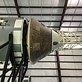
Engineers at Arnold Air Base with an Apollo service module engineApollo Service Module Propulsion System
The service propulsion system (SPS) engine was originally designed to lift the CSM off the surface of the Moon in the direct ascent mission mode,[20] The engine selected was the AJ10-137,[21] which used Aerozine 50 as fuel and nitrogen tetroxide (N2O4) as oxidizer to produce 20,500lbf (91kN) of thrust.[22] A contract was signed in April 1962 for the Aerojet-General company to start developing the engine, resulting in a thrust level twice what was needed to accomplish the lunar orbit rendezvous (LOR) mission mode officially chosen in July of that year.[23] The engine was actually used for mid-course corrections between the Earth and Moon, and to place the spacecraft into and out of lunar orbit. It also served as a retrorocket to perform the deorbit burn for Earth orbital flights.
The propellants were pressure-fed to the engine by 39.2 cubic feet (1.11m3) of gaseous helium at 3,600 pounds per square inch (25MPa), carried in two 40-inch (1.0m) diameter spherical tanks.[24]
The exhaust nozzle measured 152.82 inches (3.882m) long and 98.48 inches (2.501m) wide at the base. It was mounted on two gimbals to keep the thrust vector aligned with the spacecraft's center of mass during SPS firings. The combustion chamber and pressurant tanks were housed in the central tunnel.
Reaction control system
RCS quad containing four R-4D thrusters, as used on the Apollo Service Module
Four clusters of four reaction control system (RCS) thrusters (known as "quads") were installed around the upper section of the SM every 90°. The sixteen-thruster arrangement provided rotation and translation control in all three spacecraft axes. Each R-4D thruster measured 12 inches (30cm) long by 6 inches (15cm) diameter, generated 100 pounds-force (440N) of thrust, and used helium-fed monomethylhydrazine (MMH) as fuel and nitrogen tetroxide (NTO) as oxidizer.[25] Each quad assembly measured 2.2 by 2.7 feet (0.67 by 0.82m) and had its own fuel, oxidizer, and helium tanks mounted on the inside of an 8-by-2.75-foot (2.44 by 0.84m) skin panel. The primary fuel (MMH) tank contained 69.1 pounds (31.3kg); the secondary fuel tank contained 45.2 pounds (20.5kg); the primary oxidizer tank contained 137.0 pounds (62.1kg), and the secondary oxidizer tank contained 89.2 pounds (40.5kg). The propellant tanks were pressurized from a single tank containing 1.35 pounds (0.61kg) of liquid helium.[26] Back flow was prevented by a series of check valves, and back flow and ullage requirements were resolved by containing the fuel and oxidizer in Teflon bladders which separated the propellants from the helium pressurant.[26]
The four completely independent RCS clusters provided redundancy; only two adjacent functioning units were needed to allow complete attitude control.[26]
The lunar module used a similar four-quad arrangement of R-4D thruster engines for its RCS.
Electrical power system
Three of these fuel cells supplied electric power to the spacecraft on lunar flights.
Electrical power was produced by three fuel cells, each measuring 44 inches (1.1m) tall by 22 inches (0.56m) in diameter and weighing 245 pounds (111kg). These combined hydrogen and oxygen to generate electrical power, and produced drinkable water as a byproduct. The cells were fed by two hemispherical-cylindrical 31.75-inch (0.806m) diameter tanks, each holding 29 pounds (13kg) of liquid hydrogen, and two spherical 26-inch (0.66m) diameter tanks, each holding 326 pounds (148kg) of liquid oxygen (which also supplied the environmental control system).
On the flight of Apollo 13, the EPS was disabled by an explosive rupture of one oxygen tank, which punctured the second tank and led to the loss of all oxygen. After the accident, a third oxygen tank was added to obviate operation below 50% tank capacity. That allowed the elimination of the tank's internal stirring-fan equipment, which had contributed to the failure.
Also starting with Apollo 14, a 400 Ah auxiliary battery was added to the SM for emergency use. Apollo 13 had drawn heavily on its entry batteries in the first hours after the explosion, and while this new battery could not power the CM for more than 5–10 hours it would buy time in the event of a temporary loss of all three fuel cells. Such an event had occurred when Apollo 12 was struck twice by lightning during launch.
Environmental control system
Cabin atmosphere was maintained at 5 pounds per square inch (34kPa) of pure oxygen from the same liquid oxygen tanks that fed the electrical power system's fuel cells. Potable water supplied by the fuel cells was stored for drinking and food preparation. A thermal control system using a mixture of water and ethylene glycol as coolant dumped waste heat from the CM cabin and electronics to outer space via two 30-square-foot (2.8m2) radiators located on the lower section of the exterior walls, one covering sectors 2 and 3 and the other covering sectors 5 and 6.[27]
Communications system
VHF scimitar antennas mounted on the Service Module.
Short-range communications between the CSM and LM employed two VHFscimitar antennas mounted on the SM just above the ECS radiators. These antennas were originally located on the Block I command module and performed a double function as aerodynamic strakes to stabilize the capsule after a launch abort. The antennas were moved to the Block II service module when this function was found unnecessary.
A steerable unified S-bandhigh-gain antenna for long-range communications with Earth was mounted on the aft bulkhead. This was an array of four 31-inch (0.79m) diameter reflectors surrounding a single 11-inch (0.28m) square reflector. During launch it was folded down parallel to the main engine to fit inside the Spacecraft-to-LM Adapter (SLA). After CSM separation from the SLA, it deployed at a right angle to the SM.
Four omnidirectional S-band antennas on the CM were used when the attitude of the CSM kept the high-gain antenna from being pointed at Earth. These antennas were also used between SM jettison and landing.[28]
Specifications
Length: 24.8ft (7.6m)
Diameter: 12.8ft (3.9m)
Mass: 54,060lb (24,520kg)
Structure mass: 4,200lb (1,900kg)
Electrical equipment mass: 2,600lb (1,200kg)
Service Propulsion (SPS) engine mass: 6,600lb (3,000kg)
Apollo CSM in white for a Skylab mission, docked to the Skylab space station
The payload capability of the Saturn IB launch vehicle used to launch the Low Earth Orbit missions (Apollo 1 (planned), Apollo 7, Skylab 2, Skylab 3, Skylab 4, and Apollo–Soyuz) could not handle the 66,900-pound (30,300kg) mass of the fully fueled CSM. This was not a problem, because the spacecraft delta-v requirement of these missions was much smaller than that of the lunar mission; therefore they could be launched with less than half of the full SPS propellant load, by filling only the SPS sump tanks and leaving the storage tanks empty. The CSMs launched in orbit on Saturn IB ranged from 32,558 pounds (14,768kg) (Apollo–Soyuz), to 46,000 pounds (21,000kg) (Skylab 4).
The omnidirectional antennas sufficed for ground communications during the Earth orbital missions, so the high-gain S-band antenna on the SM was omitted from Apollo 1, Apollo 7, and the three Skylab flights. It was restored for the Apollo–Soyuz mission to communicate through the ATS-6 satellite in geostationary orbit, an experimental precursor to the current TDRSS system.
On the Skylab and Apollo–Soyuz missions, some additional dry weight was saved by removing the otherwise empty fuel and oxidizer storage tanks (leaving the partially filled sump tanks), along with one of the two helium pressurant tanks.[29] This permitted the addition of some extra RCS propellant to allow for use as a backup for the deorbit burn in case of possible SPS failure.[30]
Since the spacecraft for the Skylab missions would not be occupied for most of the mission, there was lower demand on the power system, so one of the three fuel cells was deleted from these SMs. The command module was also partially painted white, to provide passive thermal control for the extended time it would remain in orbit.
The command module could be modified to carry extra astronauts as passengers by adding jump seat couches in the aft equipment bay. CM-119 was fitted with two jump seats as a Skylab Rescue vehicle, which was never used.[31]
Major differences between Block I and Block II
Command module
Block I command module exterior
The Block II used a one-piece, quick-release, outward opening hatch instead of the two-piece plug hatch used on Block I, in which the inner piece had to be unbolted and placed inside the cabin in order to enter or exit the spacecraft (a flaw that doomed the Apollo 1 crew). The Block II hatch could be opened quickly in case of an emergency. (Both hatch versions were covered with an extra, removable section of the Boost Protective Cover which surrounded the CM to protect it in case of a launch abort.)
The Block I forward access tunnel was smaller than Block II, and intended only for emergency crew egress after splashdown in case of problems with the main hatch. It was covered by the nose of the forward heat shield during flight. Block II contained a shorter forward heat shield with a flat removable hatch, beneath a docking ring and probe mechanism which captured and held the LM.
The aluminized PET film layer, which gave the Block II heat shield a shiny mirrored appearance, was absent on Block I, exposing the light gray epoxy resin material, which on some flights was painted white.
The Block I VHF scimitar antennas were located in two semicircular strakes originally thought necessary to help stabilize the CM during reentry. However, the uncrewed reentry tests proved these to be unnecessary for stability, and also aerodynamically ineffective at high simulated lunar reentry speeds. Therefore, the strakes were removed from Block II and the antennas were moved to the service module.
The Block I CM/SM umbilical connector was smaller than on Block II, located near the crew hatch instead of nearly 180 degrees away from it. The separation point was between the modules, instead of the larger hinged arm mounted on the service module, separating at the CM sidewall on Block II.
The two negative pitch RCS engines located in the forward compartment were arranged vertically on Block I, and horizontally on Block II.
Service module
Block I service module interior components
On the Apollo 6 uncrewed Block I flight, the SM was painted white to match the command module's appearance. On Apollo 1, Apollo 4, and all the Block II spacecraft, the SM walls were left unpainted except for the EPS and ECS radiators, which were white.
The EPS and ECS radiators were redesigned for Block II. Block I had three larger EPS radiators located on Sectors 1 and 4. The ECS radiators were located on the aft section of Sectors 2 and 5.
The Block I fuel cells were located at the aft bulkhead in Sector 4, and their hydrogen and oxygen tanks were located in Sector 1.
Block I had slightly longer SPS fuel and oxidizer tanks which carried more propellant than Block II.
The Block II aft heat shield was a rectangular shape with slightly rounded corners at the propellant tank sectors. The Block I shield was the same basic shape, but bulged out slightly near the ends more like an hourglass or figure eight, to cover more of the tanks.
various tests including acoustic vibration and drop tests, and water egress training. CM was refitted with Block II improvements.[39] Underwent testing for Skylab at the McKinley Climatic Laboratory, Eglin AFB, Florida, 1971–1973.
Command module disassembled as part of Apollo 1 investigation. Service module (SM-014) used on Apollo 6 mission. Command module (CM-014) later modified and used for ground testing (as CM-014A).[33]
Never fully completed[59] – service module does not have its SPS nozzle installed. On display as part of the Saturn V display at Johnson Space Center, Houston, Texas[60]
Never fully completed[59] – internal structures not installed,[62] used for spare parts. Remaining items sent to Japan for exhibition in 1978 and never returned, display at the Space LABO in Kitakyushu,Japan.[63][64]
↑Morse, Mary Louise; Bays, Jean Kernahan (September 20, 2007). The Apollo Spacecraft: A Chronology. SP-4009II. Vol.II, Part 2(C): Developing Hardware Distinctions. NASA. Archived from the original on February 5, 2008. Retrieved April 22, 2016.
↑Orloff, Richard (1996). Apollo by the Numbers(PDF). National Aeronautics and Space Administration. p.22.
↑Day, Dwayne Allen (June 11, 2012). "Out of the black". The Space Review. Retrieved June 11, 2012.
↑Wilford, John (1969). We Reach the Moon: The New York Times Story of Man's Greatest Adventure. New York: Bantam Paperbacks. p.167. ISBN978-0552082051.
↑Gerard, James H. (November 22, 2004). "CM-007". A Field Guide to American Spacecraft. Archived from the original on January 11, 2020. Retrieved June 8, 2020.
↑"Permanent Exhibits". USS Hornet museum. December 8, 2015. Archived from the original on October 22, 2016. Retrieved October 22, 2016. the Apollo Command Module – CM-011. It was used for the uncrewed mission AS-202 on August 26, 1966
↑Gerard, James H. (July 11, 2007). "BP-22". A Field Guide to American Spacecraft. Archived from the original on January 6, 2020. Retrieved June 8, 2020.
This page is based on this Wikipedia article Text is available under the CC BY-SA 4.0 license; additional terms may apply. Images, videos and audio are available under their respective licenses.